
Dielectric Constant & Relative Permittivity
The dielectric constant & relative permittivity are key to the operation of capacitors and the determination of the levels of capacitance achievable.
Capacitance Tutorial Includes:
Capacitance
Capacitor formulas
Capacitive reactance
Parallel & series capacitors
Dielectric constant & relative permittivity
Dissipation factor, loss tangent, ESR
Capacitor conversion chart
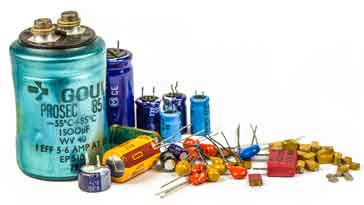
Permittivity and dielectric constant are two terms that are central to capacitor technology. Often talk will be heard of capacitors with different dielectrics being used when selections of electronic components are being made within an electronic circuit design.
Electrolytic capacitors, ceramic capacitors, paper, tantalum capacitors and all the common names for capacitors refer to the dielectric material that is used.
The dielectric material provides the insulation between the capacitor plates, and in addition this it determines many of the characteristics of the capacitor.
The dielectric of the capacitor governs the level of capacitance achievable in a certain volume, the temperature stability whether it is polarised or not. These and many other characteristics are are all a function of the dielectric material used – many properties being governed by the dielectric constant itself.
Capacitor permittivity and dielectric constant
The terms permittivity and dielectric constant are essentially the same for most purposes, although there are instances where the different terms do have very specific meanings.

It is that property of a dielectric material that determines how much electrostatic energy can be stored per unit of volume when unit voltage is applied, and as a result it is of great importance for capacitors and capacitance calculations and the like.
In capacitors, the two plates are kept apart by an insulator - this is the dielectric material that governs many of the properties of the capacitor.
Early capacitors tended to be metal plates that were kept apart by the mechanical construction of the whole assembly.
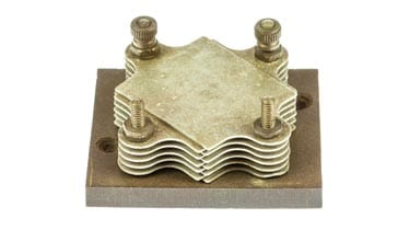
More modern capacitors have an insulating dielectric material placed between the plates. This provides two main advantages:
Separates plates: As capacitors become smaller and need to be more robust, it is necessary to place an insulating material between the plates to ensure they remain apart. With capacitors becoming very small and also very close separation between the plates being needed to have the required level of capacitance, it becomes essential to place the insulating dielectric between them.
Increases level of capacitance: By selecting the right dielectric, the level of capacitance can be increased considerably when compared to air. and it is possible to achieve very high levels of capacitance in a small volume.

The diagram shows how the way in which a very basic capacitor is constructed with a dielectric between the plates. As most of the electric filed lines pass virtually parallel between the two plates, having the dielectric only between the plates is perfectly permissible.
For real capacitors, they consist of multiple plates between each other to enable the sufficient level of capacitance to be achieved, each with a layer of dielectric insulating material between them.
Other areas where the dielectric constant is important
The dielectric constant and permittivity affect other aspects of electrical and electronic technology. The relative permittivity and dielectric constant are not just important when it comes to capacitors, there are also other areas as well.
RF transmission lines: Within coaxial and other forms of feeder the dielectric placed between the inner and outer conductors for coaxial cable, between the two wires for open feeder and between the conductor and ground plane, etc for PCB transmission lines has a major effect on the characteristics in terms of characteristic impedance and velocity factor, etc.
Radio propagation: Changes in relative permittivity of the atmosphere can have a major impact on the transmission of radio signals, especially at frequencies above 30 MHz and more. Even slight changes in relative permittivity can cause the radio signal paths to bend, often back towards the earth, causing them to be detected over greater distances.
These examples, and more show that the relative permittivity of a medium can have an impact on many aspects of electronics, radio and other elements of technology and science.
Permittivity & dielectric constant definitions
Definitions of some specific terms related to dielectric constant and permittivity are given below:
- Absolute permittivity: Absolute permittivity is defined as the measure of permittivity in a vacuum and it is how much resistance is encountered when forming an electric field in a vacuum. The absolute permittivity is normally symbolised by ε0. The permittivity of free space - a vacuum - is equal to approximately 8.85 x 10⁻¹² Farads / metre (F/m)
- Relative permittivity: Relative permittivity is defined as the permittivity of a given material relative to that of the permittivity of a vacuum. It is normally symbolised by: εr.
- Static permittivity: The static permittivity of a material is defined as its permittivity when exposed to a static electric field. Often a low frequency limit is placed on the material for this measurement. A static permittivity is often required because the response of a material is a complex relationship related to the frequency of the applied voltage.
- Dielectric constant: The dielectric constant is defined as the relative permittivity for a substance or material.
Although these terms may be seen to be related, it is often important to use the correct terms in the required place.
In general permittivity uses the Greek letter epsilon as its symbol: ε.
Relative permittivity (dielectric constant)
Using the fact that the permittivity ε of a medium is governs the charge that can be held by a medium, it can be seen that the formula to determine it is:
Where:
ε = permittivity of the substance in Farads per metre
D = electric flux density
E = electric field strength
It can be seen from the definitions of permittivity that constants are related according to the following equation:
Where:
εr = relative permittivity
εs = permittivity of the substance in Farads per metre
ε0 = permittivity of a vacuum in Farads per metre
Choice of capacitor dielectric
Capacitors use a variety of different substances as their dielectric material. The material is chosen for the properties it provides. One of the major reasons for the choice of a particular dielectric material is its dielectric constant. Those with a high dielectric constant enable high values of capacitance to be achieved - each one having a different permittivity or dielectric constant. This changes the amount of capacitance that the capacitor will have for a given area and spacing.
The dielectric will also need to be chosen to meet requirements such as insulation strength - it must be able to withstand the voltages placed across it with the thickness levels used. It must also be sufficiently stable with variations in temperature, humidity, and voltage, etc.
Popular choices for capacitors are given by the names: aluminium electrolytic capacitors, ceramic capacitors, silver mica capacitors and tantalum capacitors are all commonly used types.
Relative permittivity of common substances
The table below gives the relative permittivity of a number of common substances.
| Relative Permittivity of Common Substances |
|
|---|---|
| Substance | Relative Permittivity εr |
| Aluminium oxide | 8.6 |
| Barium Titanate (Class1) | 5 - 450 |
| Barium Titanate (Class 2) | 200 - 12000 |
| Calcium titanate | 150 |
| Ebonite | 2.7 - 2.9 |
| FR4 PCB material | 4.8 typically |
| Glass | 5 - 10 |
| Marble | 8.3 |
| Mica | 5.6 - 8.0 |
| Paper | 3.85 |
| Paraffin wax | 2 - 2.4 |
| Polyethylene | 2.25 |
| Polyimide | 2.25 |
| Polypropylene | 2.2 - 2.36 |
| Porcelain (ceramic) | 4.5 - 6.7 |
| PTFE (Teflon) | 2.1 |
| Rubber | 2.0 - 2.3 |
| Silicon | 11.68 |
| Silicon dioxide | 3.9 |
| Strontium titanate | 200 |
| Air 0°C | 1.000594 |
| Air 20°C | 1.000528 |
| Carbon monoxide 25°C | 1.000634 |
| Carbon dioxide 25°C | 1.000904 |
| Hydrogen 0°C | 1.000265 |
| Helium 25°C | 1.000067 |
| Nitrogen 25°C | 1.000538 |
| Sulphur dioxide 22°C | 1.00818 |
The values given above are what may be termed the "static" values of permittivity. They are true for steady state or low frequencies. It is found that the permittivity of a material usually decreases with increasing frequency. It also falls with increasing temperature. These factors are normally taken into account when designing a capacitor for electronics applications.
When the design of a capacitor is undertaken the characteristics of the dielectric form one of the main decisions about the capacitor.
Some materials have a very stable dielectric constant and can be used in high stability capacitors, whereas other dielectric materials enable very high levels of volumetric capacitance to be achieved, i.e. high levels of capacitance in a small volume. Normally there is a balance as no single dielectric has ideal characteristics for everything.
Although ceramic capacitors are very popular there are many different ceramics that can be used. These give rise to ceramic capacitors being denoted by the various names for the ceramic performance levels: C0G, Y5V, X7R, NP0, etc.
 Written by Ian Poole .
Experienced electronics engineer and author.
More Basic Electronics Concepts & Tutorials:
Voltage
Current
Power
Resistance
Capacitance
Inductance
Transformers
Decibel, dB
Kirchoff's Laws
Q, quality factor
RF noise
Waveforms
Return to Basic Electronics Concepts menu . . .