Op Amp Circuit Design Hints & Tips
Important guidelines, and essential hints and tips for when you are designing operational amplifier circuits.
Op-amp Tutorial Includes:
Introduction
Op amp gain
Bandwidth
Op amp slew rate
Offset null
Input impedance
Output impedance
Current feedback op amp
Understanding specifications
How to choose an op amp
Op amp circuits summary
 Check out my Op-Amp eBook. Check out my Op-Amp eBook. |
Operational amplifiers are great building blocks to use in many circuit designs and as a result they are widely used in analogue lowish frequency designs.
Being an almost perfect differential amplifier block, they can be very easy to use, but as with anything, there are a few hints, tips, guidelines and general techniques that can be employed to ensure that the circuits perform to their best.
Op-amp circuit design tips
There are many different tips and guidelines for using operational amplifiers successfully in your circuits.
This collection of tips has been put together from what I have learned over the years as an engineer, and from seeing some of the things others have done, and some of the issues that have arisen!
There are naturally very many that can be offered, but here are mine, with a few from some others who have offered their contributions.
• Choose the best op amp
There is such a wide variety of op-amps available and also many of them are at very reasonable costs.
While the general purpose op-amps like the 741 will be perfectly adequate for many circuit designs, it is worth taking a look to see whether a more sophisticated chip might suit the circuit design better.
After all there are op-amps with high input impedances, often these have FET inputs, there are low offset ones, high bandwidth, high slew rate . . . .the list goes on.
So a few minutes taken checking what might be available and whether this might be very much better than the one of the junk box or wherever.
.• Use the feedback network
The big advantage of operational amplifiers is that they have so much open loop gain, that feedback has to be used in virtually all cases so that they operate sensibly.
Having the ability to use feedback like this opens up many possibilities. The feedback can obviously be used in an amplifier to give a useful level of gain, and a flat frequency response over the useable bandwidth. However it opens up many other possibilities and these op amps can be used to give high and low pass filters, bandpass filters, notch filters, oscillators of different types . . . . All this is done using the feedback network.

There are many circuits on the internet and many on this website that provide circuits for a huge variety of functions using operational amplifiers as the basis of the circuit.
• Keep the gain down
With an op-amp having such a high level of open loop gain it is tempting to think that even with feedback, a very high level of voltage gain can be implemented.
Sadly this is not true because the very high open loop gain occurs at a frequency of only a few Hertz and above this it falls.
For voltage feedback op amps which are by far the greatest majority, the gain bandwidth product must be followed.

Although the open loop bandwidth of the op amp circuit is reduced, once negative feedback has been applied, a sufficient level gain with a flat frequency response can be achieved for most purposes.
Although there are no hard and fast rules, I tend to keep the gain down to a maximum of around 10 - 20. This allows sufficient headroom for the negative feedback to be effective and for the amplifier not to be too close to running without any feedback.
• Sensible component values
As with any circuit, it is necessary to utilise circuit values that fall within reasonable limits.
In some cases feedback resistors in amplifier circuits of 1MΩ have been seen. Also very low resistor values have been seen for the input resistor of an inverting amplifier.
These and other choices are unwise because various other circuit effects may come into play and the circuit may not perform as expected.
For the very high feedback resistors it is necessary to remember that the input resistance of many op-amps, especially general purpose ones is only about 250kΩ or so and this will affect the feedback when compared to the feedback resistor.
Also for very low input resistor values on inverting amplifiers, remember the previous stage has a source impedance and this may significantly affect the gain of the amplifier if the input resistor is designed to be too low.
These and other effects need to be thought about when selecting resistor, or for that matter any component values.
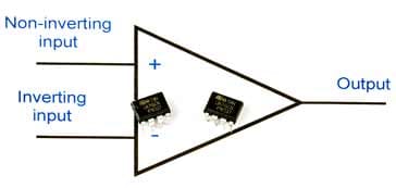
• For amplifiers: inverting or non-inverting
One of the big questions when designing a simple amplifier using an op-amp chip is whether to use the inverting or non-inverting configuration.
Both amplifiers work very well, but there are a few differences between them making one of them more suitable in certain situations.
The characteristics of each of them are summarised separately below:
Inverting amplifier
The inverting amplifier has the configuration shown in the circuit below.

It has a simple formula for the gain:
Other key features include:
Input and output are out of phase: As the name of the amplfier implies, the output is inverted, i.e. 180° out of phase when compared to the input. This often has little impact on any circuit designs, but it might be important for some.
Low input impedance: The input impedance is that of the input resistor R1. This can be ideal where a high input impedance is not needed, matching many audio requirements as well as not making the circuit so prone to pickup.
Can be used as an audio mixer: The inverting input is virtually at earth potential because the voltage difference between both inputs is very small and the non-inverting is at ground potential. This makes it ideal for being used as a virtual earth mixer for audio applications or a summing amplifier elsewhere.
The inverting amplifier is ideal for many amplifier situations, but be aware of the low input impedance.
Non-inverting amplifier
The non-inverting amplifier is ideal for many general amplifier designs and has soem distinct differences when compared to the inverting configuration.

Other key features include:
Input and output are in phase: As the name, non-inverting amplifier implies the input and output are in-phase, i.e. not inverted. Normally this has little impact on the design, but it may be important in some instances
High input impedance: One of the aspects of the non-inverting amplifier is that the input resistance is very high. This is often very useful because it does not load the previous stage. In pact, by connecting the output to the inverting input (R2 = 0) the circuit becomes a unity gain buffer.
• Remember the input current
Even though the impedance of the inputs for any op-amp is very high, the input pins still need some current.
It is important to provide a DC path for this current, and not just have a coupling capacitor to connect the input.
The resistance provided can be high, depending upon the particular chip, but a DC path is imperative.
Summary of essential tips
It is important to be aware f these and other aspects of the design for operational amplifier circuits along with any general guidelines and design aspects.
As a quick summary, check out our short video highlighting five top tips.
Video: 5 Great tips for Op-Amp Circuit Design
Operational amplifiers are ideal building blocks for many audio and low frequency circuits, although some chips are available that can provide very high frequency operation.
op-amps are freely available, most are very low cost, and they are ideal for a great number of circuit designs, being very flexible and easy to use for a host of circuits.
 Written by Ian Poole .
Experienced electronics engineer and author.
Essential operational amplifier data:-
Make your op-amp selection with op-amp data as well as distributor price and availability.
Check it out now!
More Circuits & Circuit Design:
Op Amp basics
Op Amp circuits
Power supply circuits
Transistor design
Transistor Darlington
Transistor circuits
FET circuits
Circuit symbols
Return to Circuit Design menu . . .