
Home » Component data » Transistor data » this page
MRF237 Transistor Data
Key transistor data for the MRF237 RF power transistor including key electrical parameters, pinout, package type and many other key transistor datasheet details.
The MRF237 is described as being designed for 12.5 volt large signal power amplifier applications in communications equipment operating up to 225 MHz.
At 12.5 volts and operating at 175MHz is is specified as providing 4 watts output with a minimum of 12dB gain and efficiency of 50%.
Key details and performance parameters for the 2N4427 transistor.
| Transistor Datasheet Parameters & Data |
|
|---|---|
| Parameters | Details |
| Transistor type | NPN silicon RF power transistor |
| Package type | TO39 |
| VCBO max (V) | 36 |
| VCEO max (V) | 18 |
| VEBOmax (V) | 4.0 |
| IC max (mA) | 640 continuous |
| TJ Max °C | 200 |
| PTOT W | 8 |
| fT min (MHz) | 500 |
| COB | 15pF typical 20pF max |
| hfe | 5 min |
| IC for hfe | 250 mA |
| Similar / equivalents | |
Outline:
![]()
Pinout: see below for details
Explanation of transistor parameters
| Parameter | Explanation |
|---|---|
| VCBO Max | Maximum collector-base voltage with emitter open circuit . |
| VCEO Max | Maximum collector-emitter voltage with base open circuit. |
| VEBO Max | Maximum emitter-base voltage with collector open circuit. |
| VCEsat (included where applicable) | The voltage drop across the collector-emitter when the transistor is fully saturated (acting as a closed switch). |
| IC Max | Maximum collector current. |
| Parameter | Explanation |
|---|---|
| TJ | Maximum junction temperature. |
| PTOT Max | Maximum device dissipation normally in free air at 25°C unless other conditions indicated. |
| fT Min | Minimum cutoff frequency at which the current gain in a common emitter circuit falls to unity. |
| COB Max | Maximum collector capacitane, normally measured with emitter open circuit. |
| hFE | DC current gain for HFE at IC. [Note hfe is the small signal gain and although this may be slightly different, the transistor current gain will vary considerably from ne transistor to the next of the same type.] |
| PTOT Max | Maximum device dissipation normally in free air at 25°C unless other conditions indicated. |
These are the main transistor parameters that have been included in our list. There are others, but these help quantify the main elements of the performance of the transistor.
Please note, that the data given is the best estimate we can give within a tabulated summary of this nature. Parameters also vary between manufacturers. Electronics Notes cannot accept any responsibility for errors, inaccuracies, etc, although we do endevaour to ensure the data is as accurate as possible.
Notes and supplementary information
• Availability & sources
The device is available from a very limited number of stockists and suppliers.
• Warning
The MRF237 was primarily manufactured by Motorola, but it was second sourced by Advanced Semiconductor Inc. The parameters between transistors from the two manufacturers are very similar and this makes them ideal.
However, and this is a major issue, the pin connections different between the two manufacturers. The collector and base are reversed between the two manufacturers.
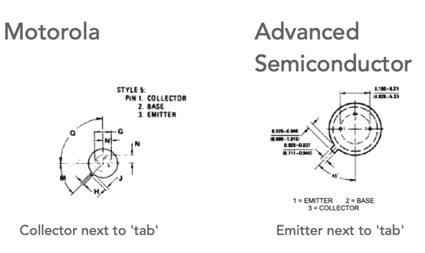
Normally it is expected that the tab on a TO39 case coincides with the emitter, but the Motorola version of the MRF237 has the collector adjacent to the tab.
The Motorola datasheet describes the device as having a grounded emitter TO39 package for high gain excellent heat dissipation, which might explain the unusual pinout.
• Applications
The MRF237 was used in many communications systems where it was an ideal RF driver or output device for HF, VHF and UHF medium power transmitters.
It was often used in commercial equipment: everything from VHF to UHF radio transceivers and handheld devices.
It was also used in some amateur radio transceivers. One example was the TenTec Argosy HF CW/SSB transceiver.
If it is necessary to replace the MRF237 as a result of a failure, then it is necessary to be aware of the pinout changes when any replacements are sourced as Motorola devices are not always easy to purchase these days.
 Written by Ian Poole .
Experienced electronics engineer and author.
Return to Component Data menu . . .