Home » Component data » Transistor data » this page
OC72 Transistor Data
Key transistor data for the OC72 PNP audio germanium transistor for output stages including key electrical parameters, pinout, package type and many other key transistor datasheet details.
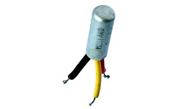
The OC72 was an audio low power output amplifier housed in a metal encapsulation to provide protection of the device.
Key details and performance parameters for the OC72 transistor.
| OC72 transistor datasheet parameters & data |
|
|---|---|
| Parameters | Details |
| Transistor type | PNP germanium audio transistor |
| Package type | X02 |
| VCBO max (V) | -16 |
| VCEO max (V) | -16 |
| VEBOmax (V) | -10 |
| IC max (mA) | 125 |
| TJ Max °C | 80 |
| PTOT mW | 165 |
| fT min (MHz) | 0.25 |
| COB | 40 |
| hfe | 30 min |
| IC for hfe | 80 mA |
| Similar / equivalents | |
Outline:
![]()
Pinout:
![]()
Explanation of transistor parameters
| Parameter | Explanation |
|---|---|
| VCBO Max | Maximum collector-base voltage with emitter open circuit . |
| VCEO Max | Maximum collector-emitter voltage with base open circuit. |
| VEBO Max | Maximum emitter-base voltage with collector open circuit. |
| VCEsat (included where applicable) | The voltage drop across the collector-emitter when the transistor is fully saturated (acting as a closed switch). |
| IC Max | Maximum collector current. |
| Parameter | Explanation |
|---|---|
| TJ | Maximum junction temperature. |
| PTOT Max | Maximum device dissipation normally in free air at 25°C unless other conditions indicated. |
| fT Min | Minimum cutoff frequency at which the current gain in a common emitter circuit falls to unity. |
| COB Max | Maximum collector capacitane, normally measured with emitter open circuit. |
| hFE | DC current gain for HFE at IC. [Note hfe is the small signal gain and although this may be slightly different, the transistor current gain will vary considerably from ne transistor to the next of the same type.] |
| PTOT Max | Maximum device dissipation normally in free air at 25°C unless other conditions indicated. |
These are the main transistor parameters that have been included in our list. There are others, but these help quantify the main elements of the performance of the transistor.
Please note, that the data given is the best estimate we can give within a tabulated summary of this nature. Parameters also vary between manufacturers. Electronics Notes cannot accept any responsibility for errors, inaccuracies, etc, although we do endevaour to ensure the data is as accurate as possible.
Notes and supplementary information
The OC72 was designed as a transistor for use in low power audio output stages. There was no complementary, i.e. NPN transistor because at this time most transistor radios that would utilise these transistors used audio transformers and therefore a push-pull, class B amplifier could be made using two PNP OC72s.
Although it was capable of only providing a low power output, it was nevertheless ideal for many of the transistor radios of the day for which high output levels were not expected.
• Timeline
The OC72 was introduced in 1955 as an output transistor and the first offerings were encapsulated in a glass case similar to that of the OC71 but longer in length.
The OC72 utilised a number of new developments from Philips / Mullard to provide a higher power handling capacity:
All glass hermetic seal: the company developed an all glass hermetic seal using silicone grease and this not only protected the active elements but it also provided improved heat transfer.
Dopant advances: The principal dopant for the semiconductors at the time was indium. However advances were made by using what were called co-dopants such as gallium and this gave a significantly improved power handling capability which was used in the OC71.
Encapsulation: The encapsulation for the OC72 underwent development. The initial offerings were in a slightly taller version of the encapsulation used for the OC71 and similar transistors, but a new encapsulation using a metal outer case was developed and this gave improved power handling.
Over the production life of the OC72, some improvements in performance were seen, and this can be attributed to improvements in the technologies used it he fabrication of the devices.
 Written by Ian Poole .
Experienced electronics engineer and author.
Return to Component Data menu . . .