Understanding Diode Rectifier Circuits
Diode rectifier circuits come in many forms ranging from simple diode half wave rectifiers, to full wave rectifiers, those using bridge rectifiers, voltage doublers and many more.
Diode Rectifier Circuits Include:
Diode rectifier circuits
Half wave rectifier
Full wave rectifier
Two diode full wave rectifier
Full wave bridge rectifier
Synchronous rectifier
Diode rectifier circuits are one of the key circuits used in electronic equipment. They can be used in switch mode power supplies and linear power supplies, RF signal demodulation, RF power sensing and very much more.
There are several different types of diode rectifier circuit, each with its own advantages and disadvantages. Decisions about which type of diode circuit to use depend upon the given situation.

Diode rectifier circuit basics
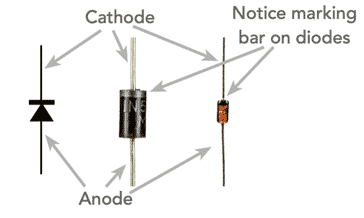
The key component in any rectifier circuit is naturally the diode or diodes used. These devices are unique in only allowing current through in one direction, and blocking the current flow in the other.
Interestingly Ambrose Fleming who invented the first form of diode - a thermionic diode - called his version a valve because of its one way action. Semiconductor diodes now perform the same function, but occupy a fraction of the space and are normally only a small fraction of the cost.

The semiconductor diode has a characteristic something like that shown in the graph. In the forward direction, a small voltage is required across the diode before it conducts - this is known as the turn on voltage.
The actual turn on voltage depends on the type of diode rectifier and the material used. For a standard silicon diode rectifier this turn on voltage is around 0.6 volts. Germanium diodes have a turn on voltage of around 0.2 - 0.3V, and silicon Schottky diodes have a similar turn on voltage, i.e. in the region of 0.2 - 0.3V.
In the reverse direction, the diode rectifier will pass very little current. There is a small leakage current, but for the rectifier diodes used today, this can usually be ignored.
However it is worth remembering that as the reverse voltage is increased, the diode wil ultimately break down. The breakdown voltage is normally well in excess of the turn on voltage - the scales on the diagram have been altered (compressed) in the reverse direction to illustrate that reverse breakdown occurs.
Note on the Diode Types:
Although the basic function of a diode remains the same, the there are many different types with slightly different characteristics. Some many be optimised for power rectification, others for signal rectification, others use the diode junction to emit light, or have a variable capacitance, etc.
Read more about the Types of Semiconductor Diode.
For power rectification applications, power diodes or Schottky diodes are normally used. For signal rectification small point contact diodes, signal diodes, or Schottky diodes may be used. The lower forward turn on voltage for Schottky diodes is a distinct advantage for RF detector diodes where signal levels may be small and even the turn on voltage level can be very important. However the reverse leakage characteristics are not as good as normal silicon diodes.
Diode packages
Semiconductor didoes come in a huge variety of packages. They are available as leaded diodes, some small signal diodes are available in leaded glass packages, whereas others are available in plastic leaded packages.

For higher power applications, some diodes are available in packages that can be bolted to heatsinks. These are intended for very much higher current circuit designs where significant levels of heat might be dissipated as a result of the forward voltage drop and also the current drawn.
There is also a good selection of surface mount diodes. With the increasing use of automated production, surface mount technology, and the surface mount diodes are being used increasingly. Naturally their power dissipation may not be sufficient for high power designs, but they are nevertheless suitable for many electronic circuit designs.
Another type of diode package is a bridge rectifier. This consists of four diodes in a single package connected to provide a full wave rectifier. These bridge rectifiers are very useful as they mean that only one device rather than four is needed.
Diode rectifier action
The action of the diode is to allow current to flow in only one direction. Therefor is an alternating waveform is applied to a diode, then it will only allow conduction over half the waveform. The remaining half is blocked.

Diode rectifier circuit configurations
There are a number of different configurations of diode rectifier circuit that can be used. These different configurations each have their own advantages and disadvantages, and are therefore applicable to different applications.
Half wave rectifier circuit: This is the simplest form of rectifier. Normally it only uses a single diode which blocks half the cycle and allows through the other half. This means that only half the waveform is used.
While the advantage of this circuit is its simplicity, the drawback is the fact that there is longer between successive peaks of the rectified signal. This makes smoothing less effective and it is more difficult to achieve high levels ripple rejection.
This circuit is not normally used for any power supply applications - it is more commonly used for signal detection and level detection applications.
Read more about . . . . Half Wave Rectifier Rectifier.
Full wave rectifier circuit: This form of rectifier circuit uses both halves of the waveform. Accordingly this form of rectifier more efficient, and as there is conduction over both halves of the cycle, smoothing becomes much easier and more effective.
There are two types of full wave rectifier.
Two diode centre taped transformer full wave rectifier: The two diode version of the full wave rectifier circuit requires a centre tap in the transformer. When vacuum tubes / thermionic valves were used, this option was widely used in view of the cost of the valves. However with semiconductors, a four diode bridge circuit saves on the cost of the centre tapped transformer and is equally effective.
Read more about . . . . Full Wave Two Diode Rectifier.
Bridge full rectifier circuit: This is a specific form of full wave rectifier that utilises four diodes in a bridge topology. Bridge rectifiers are widely used, especially for power rectification, and they can be obtained as a single component contain the four diodes connected in the bridge format.
This format uses four diodes, two conducting in each half of the cycle. This does mean that there are two diode voltage drops which can dissipate some power, but is saves on the requirement for a centre tapped transformer, which makes a significant cost saving. Also the diodes do not need to have such a high reverse voltage rating as those used in the two diode configuration.
In view of the fact that there are two diode voltage drops, this circuit is seldom used for signal detection applications. However it is very suitable for use in linear power supplies and also in many cases in switch mode power supplies.
Read more about . . . . Bridge Rectifiers.
Synchronous rectifier circuit: Synchronous or active rectifiers use active elements instead of diodes to provide the switching. This overcomes the diode losses and significantly improves the efficiency levels.
In view of the greater levels of efficiency that synchronous rectifiers can provide, they are being used very widely in high efficiency switch mode power supplies. Their complexity is more than outweighed by the much higher efficiency levels attainable.
Read more about . . . . Synchronous Rectifiers.
Rectifier circuits summary
Different rectifier circuits have different properties, characteristics and capabilities. Some are applicable to some situations, whereas other circuits to different situations.
In order to select the best circuit for the particular circuit and situation, it helps to have a quick summary of the various common rectifier circuit configurations:
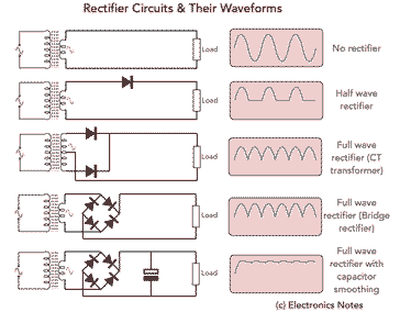
- No rectifier: The output from the transformer is applied directly to the load and it sees a full wave alternating voltage.
- Half wave rectifier: A single diode is used to provide half wave rectification. Half the waveform is passed through leaving the remain half blocked. The peak of the waveform of 1.414 times the RMS value of the transformer output less a single diode drop.
- Full wave rectifier using a centre tapped transformer: This circuit uses two diodes to provide full wave rectification utilising both halves of the waveform. The peak voltage output is 1.414 times the RMS voltage from the transformer less a single diode drop. The disadvantage is that this requires a more expensive transformer and each half of the winding is only used for half the cycle.
- Full wave rectifier using bridge rectifier: This circuit uses a transformer with a single winding and no centre tap on the output to provide full wave rectification. The peak output voltage is 1.1414 times the RMS voltage of the transformer output less two diode drops.
- Full wave bridge rectifier with smoothing: This circuit uses a full wave bridge rectifier with a capacitor to provide smoothing. Some ripple remains as can be seen, but it is much better than if a half wave rectifier had been used. A voltage regulator may be used to provide a fully regulated output.

Click on image for larger version
It is worth noting the output voltage from the transformer will fall as the current drawn increases due to internal resistance, etc.
In view of the variety of different types of rectifier circuit, there is a good choice of which type to use. In many cases this is dictated by the level of performance required, and in most cases a form of full wave rectifier is needed. With the availability and low cost of bridge rectifiers, this is normally the cheapest option, rather than saving on the diodes and then requiring a centre taped transformer.
With modern power supplies requiring ever higher levels of efficiency, many designers are looking to the use of synchronous rectifiers. Although they are more complicated and therefore cost more, this cost is often worth the returns they give in increasing the efficiency level.
 Written by Ian Poole .
Experienced electronics engineer and author.
More Circuits & Circuit Design:
Op Amp basics
Op Amp circuits
Power supply circuits
Transistor design
Transistor Darlington
Transistor circuits
FET circuits
Circuit symbols
Return to Circuit Design menu . . .


