7800 Series Voltage Regulators: 7805, 7812, 7824, etc
The 7800 or 78xx series voltage regulators including the 7805, 7812, 7815, 7824, etc are very easy to use to provide linear voltage regulator for power supplies.
Linear Power Supply Circuits Primer & Tutorial Includes:
Linear power supply
Shunt regulator
Series regulator
Current limiter
Constant current vs foldback limiting
78** series regulators & circuits
LM317 voltage regulator & circuits
LDO, low dropout regulators
See also:
Power supply electronics overview
Switch mode power supply
Capacitor smoothing
Over-voltage protection
PSU specs
Digital Power
Power management bus: PMbus
Uninterruptible power supply
For many years the 7800 or 78xx series linear voltage regulators, including the more popular versions of this series like the 7805, 7812, etc, were the most popular voltage regulator chips available and they were used in many electronic circuits, large and small.
The 7800 series voltage regulators were very easy to use, they were cheap to buy, and they provided excellent performance.
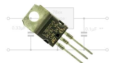
Although now they are a little dated, they can still be obtained very cheaply and provide excellent performance, and they often remain designated as "Active" components that are likely to remain available for many years to come. This makes them an ideal choice for many electronic devices and circuits, especially for the home constructor, etc.
Not only was there the 7800 series of linear voltage regulators giving a positive output voltage, but there was also the complementary 7900 series regulators used for negative voltage lines.
7800 series voltage regulator specifications
The 7800 series voltage regulators are very easy to use, and their specifications mean that they can be used very easily in a variety of voltage regulator and linear power supply applications.
| 7800 Voltage Regulator Variants & Specific Specifications |
||||
|---|---|---|---|---|
| Parameter | IC Number | Min | Max | Unit |
| Input voltage | 7805 | 7 | 25 | V |
| 7808 | 10.5 | 25 | V | |
| 7810 | 12.5 | 28 | V | |
| 7812 | 14.5 | 30 | V | |
| 7815 | 17.5 | 30 | V | |
| 7824 | 27 | 38 | V | |
| Output current, IO | 1.5 | A | ||
| Operating junction temperature, TJ | 7800 series | 125 | °C | |
The other electrical characteristics vary slightly across the range and therefore the 7805 has been selected as one of the most widely used.
Specifications for other 7800 series voltage regulators like the 7812 can be estimated from the 7805 as they have similar overall characteristics, but modified for the particular device voltage.
| Specifications for various 7805 series voltage regulator parameters |
||||
|---|---|---|---|---|
| Parameter & conditions | Min | Typical | Max | Unit |
| Output voltage @ 25°C | 4.8 | 5.0 | 5.2 | V |
| Output voltage 0°C to 125°C | 4.75 | 5.25 | V | |
| Input voltage regulation @° 25°C VI = 7V to 25V | 3 | 100 | mV | |
| Ripple rejection, VI 8V to 18V f=120Hz | 62 | 78 | dB | |
| Output voltage regulation, IO 5mA to 1.5A | 15 | 100 | mV | |
| Output resistance, f=1kHz | 0.017 | Ω | ||
| Temperature coefficient of voltage, IO 5mA | -1.1 | mV/°C | ||
| Drop out voltage, IO = 1A | 2 | V | ||
| Short circuit output current @25° C | 750 | mA | ||
| Peak output current @25°C | 2.2 | A | ||
These specifications for the 7805 voltage regulator provide the specifications for this variant, but bear in mind the specification will vary slightly between different manufacturers, and also they give a sense of the sort of capabilities for the other variants, 7808, 7812, 7815, 7824, etc.
7800 series voltage regulator packages
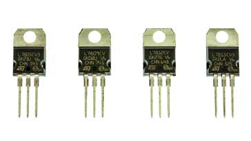
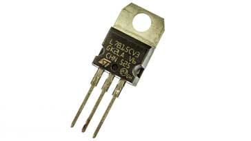
The main package fo the 7800 series regulators: everything from the 7805 and 7808 to the 7812 and 7812, etc is the TO220 package.
The pinout is very simple - there are three connections, namely: input, output and common. The metal on the package is connected to common, so this is ideal for mounting onto heatsinks which are normally mechanically and electrically connected to the ground of the system.

The metal mounting / fixing point is connected to the ground pin. Under most operating conditions, the ground pin is the same as the electrical ground, but be careful if using the regulator in a variable voltage configuration where it may need to sit above ground. In this case an insulating washer set is required when bolted to a heatsink.
7800 series power variants
Although the main type of 7800 series regulators use the TO220 style package and provide a 1.5 amp output, there are also other variants that are capable of providing different power levels.
Although many of the basic specifications remain the same, the power limits are different, enabling them to be incorporated into different packages.
In this way they can be used in many different areas, providing larger output levels of an amp of more for main power supply functions, or as smaller on-board regulators for a section of circuitry..
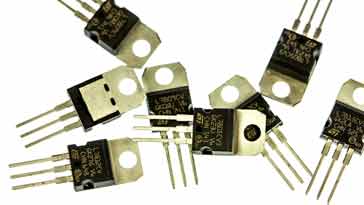
These variants are designated by placing a letter such as H, for high power, M for medium power and L for low power into the part number.
| Regulator Series | Typical Max Current (A) | Common Package Types |
|---|---|---|
| 7800 | 1.0 to 1.5 | TO220 |
| 78H00 | 5 | TO3 |
| 78M00 | 0.5 | TO126 |
| 78L00 | 0.1 | TO92 |
Note: The actual maximum current rating for the voltage regulator integrated circuits may vary slightly from one manufacturer to the next. Those value given are typical, and given by most of the devices in a particular range, but check with the actual specification before needing to run them close to the maximum values stated.
Find out Voltage Regulator Data:
Check out the data for a large variety of voltage regulators along with the distributor stock levels and prices.
Find out more about Voltage Regulator Chips & Data
Advantages & disadvantages of 7800 regulators
Although the 78xx series regulators offer a very good solution for a linear voltage regulator in many instances, it is worth looking at both the advantages and disadvantages of using these voltage regulator circuits.
78xx series regulator advantages
- Very easy to use - just select the required 7800 series regulator and place it in circuit for it to work.
- Very few additional electronic components are required - using the basic circuit only capacitors are required for the input and output.
- Low cost - these linear voltage regulators can be obtained for a very low cost.
78xx series regulator disadvantages
- The 7800 series regulators are old technology, and more modern integrated circuits would normally be used these days.
- They are a voltage linear regulator, and therefore they offer a low efficiency compared to switch mode power supplies.
- The voltage regulator chip requires a voltage dropa cross it to work - typically this voltage is around 2.5V minimum, and more is better.
Basic 7800 series voltage regulator circuit
The electronic circuit design using 7800 series voltage regulators is very easy. It is almost a matter of putting them in circuit: input, output and ground.
Naturally there are a few additional electronic components that may be required to ensure the correct operation of the voltage regulator circuit.

* This capacitor is required to ensure the stability of the regulator. Normally if the smoothing capacitor for the rectifiers is close, then this can be omitted, but if there is any length of wire, then it must be included to ensure the circuit remains stable.
** This capacitor is in circuit to remove noise and transients.
This is the basic circuit used for any 7800 series voltage regulator. It is very successful and requires no additional components beyond those shown for the basic operation.
7800 series voltage regulator negative supply circuit
Although there are the 7900 series regulators for negative supplies, there are some occasions when a negative supply regulator is required and one may not be available, or it may be necessary to reduce the electronic component count.
Either way it is possible to use a 7800 series regulator with a few changes tot he circuit to regulate a negative voltage line.

Important note: For this circuit to be able to operate correctly, both input terminals (Vi) must be floating. If they are earthed then the regulator output will be shorted and it will not operate.
Variable voltage regulator circuit
Even though the 7800 series regulators are essentially fixed voltage regulators, by using some careful electronic circuit design, it is possible to be able to adjust the output.
To achieve the variable output voltage, it is necessary to raise the potential of the common line, by adding a few additional electronic components.
The overall regulator performance is not quite as good as if the common line was taken directly to ground, but it is still very good for most applications.

The value of the components and the output voltage can be determined from the equation below:
Where
Vxx = the voltage of the regulator, i.e. 12 volts for 7812
IO = current in common line
When calculating the values for the resistors, be aware that the current drawn by the common connection is typically around 5mA and not the more normal value of around 5µA drawn by a regulator chip like an LM317 that has been designed to operate in this mode. Ensure that the resistors are low enough so that this current can be accommodated.
The variable regulated power supply using a 7800 series integrated circuit is a useful way of providing some voltage variation using one of these very useful electronic components.
7800 / 7900 series dual supply
With operational amplifiers and many other circuits requiring dual, i.e. positive and negative rails, it is often useful to have a power supply with voltage regulators that provide both positive and negative supplies.
The 7800 series voltage regulators are ideal for providing the positive rail, and their cousins the 7900 series regulators provide the same but for negative rails. In this way the two voltage regulator chips complement each other as they were intended.
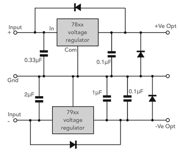
The dual linear voltage regulator circuit is very self explanatory. The circuit is relatively tolerant to the actual capacitor values, but err on the larger rather than smaller side, ensuring that the 0.1µF and 0.33µF capacitors are around these values to remove and RF for which electrolytic capacitors will not perform nearly as well.
Electrolytic capacitors tend to have an upper frequency limit of very approximately 100 kHz as a result of the electrolytic action that gives them their capacitance.
This dual linear voltage regulator circuit is easy to construct, using relatively few electronic components and it works very well.
7800 circuit design tips
As with any chip or circuit design, there are always some useful tips to ensure it works to provide the best performance.
Here are a few tips that I have gained over the years:
Input capacitor: It's always wise to place a capacitor of about 0.2 to 0.5µF close to the chip between the input and the ground pins. This helps ensure the stability of the regulator chip. If it is not present and the wiring from any smoothing capacitor to the chip is long, of there is too much inductance or high series resistance in the smoothing capacitor, then the 7800 chip can become unstable.
Output capacitor: Again, it is wise to have a small capacitor - typically about 0.1µF on the output of the regulator chip - this helps remove any transients that may be present.
Minimum load: The 7800 regulators do like operating into a no-load or very small load and they can become unstable under these conditions. This is not always well highlighted in the data-sheets, so it is always best to place a small load on the output if there is any likelihood of the main load being removed.
The 7800 series voltage regulator integrated circuits are one of the most useful regulator ICs ever made. Whilst other types have overtaken them in various aspects, the 7800 chips are still widely available and used in great quantities. The chips can be bought from a variety of stockists and distributors.
 Written by Ian Poole .
Experienced electronics engineer and author.
More Circuits & Circuit Design:
Op Amp basics
Op Amp circuits
Power supply circuits
Transistor design
Transistor Darlington
Transistor circuits
FET circuits
Circuit symbols
Return to Circuit Design menu . . .


