Crystal Radio Set Components & Parts
Crystal radio sets use a limited number of components - in the early days of radio these were bought or made, and today it is still possible to obtain the components.
Crystal Radio Sets History Includes:
Crystal radio sets
Crystal radio circuits
Crystal detector
Crystal radio components
Iconic radio receivers:
Summary of iconic radio receivers
Radio receiver history
Radio history / timeline
The circuits for crystal radio sets are relatively straightforward. They require comparatively few components.
In the heyday for crystal sets in the 1920s crystal sets could be bought and made. Sometimes people made the actual components, other times they might buy the components, or they could buy kits to make at home, or they could buy the ready made crystal sets.
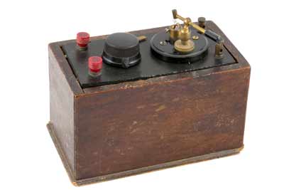
During the 1920s there were hundreds of small companies that manufactured crystal radio sets, and they often manufactured their own components, or bought some of the more difficult to make ones from suppliers.
Today, it is still possible to make or build a crystal radio set without too much expenditure.
Crystal radio components
Although a variety of circuits can be used for a crystal radio, the simplest form is shown in the diagram below. This uses just four components and serves to illustrate what component parts are needed.
Obviously more complicated circuits can be used, but these have the added complexity of requiring a few more components, or more complicated ones.

The main components required for crystal sets were inductors, capacitors, diodes (cat's whiskers), and headphones. A huge variety were available then, and these components can still be made or bought today.
Looking at antique radios, it is possible to see the techniques that were used int he 1920s. Technology has moved on significantly in all areas, so today different materials are available, although some of the original ideas and concepts can still be put into practice if a modern crystal radio set is to be made.
Coil or inductor
In the original crystal vintage radios, this component could take a variety of forms. The coils were sometimes made on cylinders, on small formers or as a flat format where the wire was almost weaved on a flat circular shape with radiating slits cut in the base material so the wire could be wound on it and kept in place.
Some crystal radio designs incorporated inductors that had taps in the winding, or they might have had two windings so they were able to act as an RF transformer and give some degree of impedance matching.
Some transformer-inductors even had the capability to change the coupling between windings. This enabled the selectivity and sensitivity to be changed according to the reception conditions. The mechanical assemblies tended to be commercially manufactured although some capable home constructors did make their own.
In general, these inductors were wound on a variety of types of former. Some of which were bought and others made out of suitable materials that could be obtained. In the days of the early crystal sets plastic was not available as it is today, so other materials were adopted.
For the home constructor today, an inductor for the crystal radio can be made relatively easily. Typically it will need to be wound on a cylindrical former. Often card cylinders for wrapping paper or kitchen roll provide an easy-to-use base that is widely available.
Plastic pipe can also provide a good base as well. Other coils can be made from discarded transistor radios. Often these radios have ferrite rod antennas, which could form the basis of the coil. Although not in any way authentic, the circuit will work.
Tuning capacitor
In the original crystal set vintage radios, the tuning capacitor component could be in one of a variety of forms.
Often these electronic components had a series of vanes alternately connected to different connections of the capacitor. The vanes could be moved in and out, the degree of meshing altering the capacitance.
These variable capacitors were expensive to make and were costly. Good quality variable capacitors were used in vintage radios using valves / tubes. Very occasionally radios that are well past restoration might be able to provide a suitable capacitor.
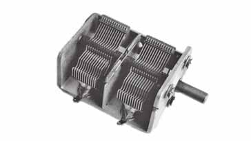
Another alternative is to utilise a small plastic variable capacitors from a old non-working transistor radio as these are much more likely to be found in attics, old sheds and the like.
The capacitor needs to be extracted by carefully unsoldering it. Care needs to be take not to damage the capacitor. It will typically have three connections. It will have two sections, so one connection for each variable capacitor section and a common earth or ground connection. This common connection is most likely to be in the centre.
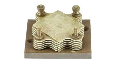
Signal diode
The signal detector diode rectifies the incoming signal so that the modulation can be heard. As the signal levels are low, a key property of the diode is that it can provide rectification at very low levels.
The original crystal detectors were the cat’s whisker style detectors were able to achieve this. They consisted of a small piece of the rectifier material of crystal held in a holder onto which a thin piece of wire would be placed. This created a point contact diode an allowed the signal to be rectified and hence detected or demodulated.
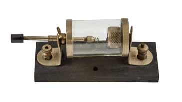
Quite specialised mechanical holders were made for the crystals. These not only had an arrangement for holding the crystal, but also a method of holding the thin wire so that it could be placed on different positions of the crystal.
Today small glass packaged germanium signal diodes like the e.g. OA47, OA90, OA91, IN34 etc. can be used. These diodes, rather than silicon diodes must be used because germanium diodes have a much lower turn on voltage, around 0.2V rather than the 0.6V of the silicon diodes. Schottky diodes an also be used as these have a low turn on voltage as well. Ordinary silicon diodes just will not work.
The germanium and Schottky diodes have a very similar IV characteristic to that of the cat's whiskers found in the vintage radios of the 1920s or earlier. Not only is the turn on or knee voltage lower, but soem rectification also takes place at lower voltage.

Both germanium and Schottky diodes are widely available for a few pence in fact they will probably be the cheapest components in the crystal radio set.
Headphones
The headphones used with a vintage radio crystal set needed to be high impedance versions. Originally high impedance moving coil headphones were used. Often these were based around the earpieces used in telephone handsets, and also the headsets were often quite uncomfortable.
These headphones were made by a variety of manufacturers. S G Brown was one such manufacturer in the UK, but many other companies were building headphones for crystal radio receivers. The higher the impedance and the greater the sensitivity, the better they worked. Low impedance ones would present too much of a load for the very small signal levels that were received from the antennas and hence they would not work.

Today small high impedance piezo based ear pieces are likely to be suitable as they have a high impedance and a good level of sensitivity. Typically a single earpiece is used as any stations received will only be transmitting monaural signals and two earpieces would reduce the signal strength.
Building a kit crystal radio set
Although it is not always easy to obtain the basic components for a crystal radio set individually, there are a few places where it is possible to buy a simple kit radio. Buying a kit radio is probably the cheapest way of buying the components as sometimes they can be quite expensive, and also ascertaining the right number of turns ont he inductor can be difficult.These may often be labelled as teaching aids, and they have all the components needed, and also often have a wiring board for all the components, making them very easy to wire up.
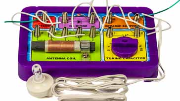
Typically these kits will include a coil or inductor wound on a ferrite rod - this will enable it to provide better selectivity than coils wound on an open former, and it will also mean that the coil requires fewer turns.
The variable capacitor provided within a kit will be similar to those found in transistor radios, and the overall circuit will be designed to enable the capacitor to provide the required tuning range.
The type of diode that is used is also important. For a crystal set, it is important to use a form of diode known as a Schottky diode which has a lower "turn-on" voltage and hence it can rectify or detect signals with a lower strength.
For the headphones of earpiece, these days a high impedance piezo-electric earpiece will be used - this gives good sensitivity and a very high impedance which will not unduly load the crystal set circuit.
Even with a kit crystal set radio and good aerial or antenna will be needed. As the radio does not have an amplifier in it, all the power to drive the earpiece comes from the antenna, so this needs to be high and long so that it can receive sufficient signal to drive the circuit properly.
One word of warning: crystal set radios should bever be operated during an electrical storm or when one might occur. High voltages could be generated within the antenna and these could be dangerous.
The components for crystal radio sets can be obtained relatively easily and items like coils or inductors can be made from items, many of which can be found around the home. Although not sensitive, experimenting with the different circuits and different components can help to build a radio se that can receive soem local stations on the medium wave band.
 Written by Ian Poole .
Experienced electronics engineer and author.
More History:
Radio history timeline
History of the radio
Ham radio history
Coherer
Crystal radio
Magnetic detector
Spark transmitter
Morse telegraph
Valve / tube history
PN junction diode invention
Transistor
Integrated circuit
Quartz crystals
Classic radios
Mobile telecoms history
Vintage mobile phones
Return to History menu . . .


