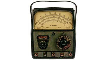
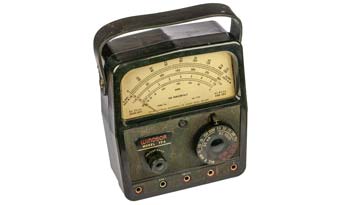
Windsor 77A Analogue Multimeter
The Windsor 77A is a vintage analogue multimeter manufactured by Taylor Instruments of Slough, dating from the mid 1950s and capable of providing excellent service.
Vintage Test Equipment Includes:
Windsor 77A Multimeter
Taylor 127A Multimeter
The Windsor 77A was an analogue multimeter introduced in the mid 1950s as a competitor to the AVO series of multimeters that had gained a large market share in the UK.
Designed and built by Taylor Instruments of Slough, it had a large dial face and was able to provide readings of current, voltage and resistance.

As with many other Taylor multimeters, a leather case was also available and this has meant that a good proportion of them have remained in good condition over many years.
| Brief Specification for the Windsor 77A Analogue Multimeter or Test Meter |
|
|---|---|
| Parameter | Specification |
| DC Volts | 0-7.5, 0-30, 0-75, 0-300, -0-750, 0-3000 |
| AC Volts | 0-7.7, 0-30, 0-75, 0-300, 0-750 |
| DC mA | 0-0.15, 0-1.5, 0-15, 0-150, 0-1.5A, 0-15A |
| Resistance | 10Ω - 50 kΩ and 1000Ω to 5mΩ |
| Extra ranges | The 7.5V DC range may be used to measure 0-50µA DC and similarly the 7.5V AC range to measure 0-200µA AC (use the relevant current inputs instead of the voltage input.) |
| Sensitivity | 20 000 ohms per volt DC 5 000 ohms per volt AC |
| Accuracy | Within: ±2% of full scale on all DC ranges except 3 000 volts ±3% of full scale on 3 000 volts DC range ±4% of full scale on all AC ranges ±7% at centre scale on both AC ranges |
| Frequency response | On AC ranges and output sockets the frequency response is sensibly flat up to 100 kc/s. |
The Windsor 77A multimeter was developed as a very good performance meter for a variety of uses and would have been one of the higher-end meters for its day.
Development and history
Although meters have been available for many years, the galvanometer was invented in 1820, but it was not until a British Post Office engineer named Donald Macadie wanted a meter that would measure the three basic quantities of current voltage and resistance in one unit, that he designed one for his use.
This meter was called the AVO meter because it measured Amps, Volts and Ohms.
The AVO meter provided to be so useful that many other companies started to design and manufacture them. One of these was Taylor Instruments which was based in Slough to the West of London. They became renowned for their high quality meters.
This particular instrument was designed around 1955 and provided a high quality, and easy to read instrument for its day.
Later as digital multimeters became more widespread as well as more meters coming in from the Far East the market became more difficult and Taylor merged with AVO and was then they taken over.
Circuit description
The Windsor 77A multimeter was built within a large-ish Bakelite case and it contained all the precision resistors and the like to enable the meter to function as a very capable meter of its day.
The circuit used a high quality switch, with beryllium copper contacts, which as the handbook states is used to give trouble free life.
The meter had two diodes wired in parallel across it to prevent overload of the meter, although as the handbook stated, it would not prevent burn-out of any resistors if a significant overload was placed on it.
As with any multimeter, analogue, or digital, it is always best to return the switch to the position of highest voltage to prevent accidental overload.
The meter movement itself is a high grade one manufactured by Taylor Instruments, and it provides a high torque-weight ratio enabling it to come to the final position for the reading very quickly.
Interestingly, the meter mounts use spring loaded jewel bearings to give smooth trouble free operation, and the fact that they are spring loaded means that they are able to withstand greater shock levels than meters with fixed jewel bearings.

Windsor 77A operation
The operation of the Windsor 77A multimeter followed the same pattern of other multimeters. Although some of the controls might be slightly different, the basic operation was quite standard.
The handbook states that the meter can be used both horizontally or flat on a work bench or vertically - there is a zero adjustment as the zero point changes as the orientation of the meter is changed.
The basic operation of the meter follows the same process that is used with virtually all meters, and the usual precautions should be observed with care being taken to read the emter, ensuring that it is viewed at right angles to the needle and the meter face.
One interesting feature is the buzzer position that can be accessed via the front main switch. This provides a useful audio check of continuity.
An audible continuity check was soemthing of a novelty in the days when this was produced, but now of course many meters have this capability.
The handbook or instruction manual states that the continuity buzzer capability can be useful for Morse practice if the meter leads are connected to a Morse key!
 Written by Ian Poole .
Experienced electronics engineer and author.
More History:
Radio history timeline
History of the radio
Ham radio history
Coherer
Crystal radio
Magnetic detector
Spark transmitter
Morse telegraph
Valve / tube history
PN junction diode invention
Transistor
Integrated circuit
Quartz crystals
Classic radios
Mobile telecoms history
Vintage mobile phones
Return to History menu . . .


