Dipole Antenna Length: calculation & formula
Notes and details about the dipole antenna length calculation & formula for a half wave dipole.
Home » Antennas & Propagation » this page
Dipole Antennas Include:
Dipole antenna basics
Current & voltage
Half wave dipole
Folded dipole
Short dipole
Doublet
Dipole length
Dipole feeds
Radiation pattern
Build HF ham dipole
Inverted V dipole
HF multiband fan dipole
HF multiband trap dipole
G5RV antenna
FM dipole design
The length of a dipole is the main consideration for determining its operating frequency. Often dipoles are designed to form a half wavelength at their operating frequency
As a result, calculating the length of a dipole antenna is a key element of designing and installing any one whether for HF, VHF, or UHF, etc., for broadcast reception, transmission or for two way radio communications, such as point to point links amateur radio, for reception or any application.

Most dipole antennas are a half wavelength long, and accordingly it is often necessary to calculate the physical length of a half wavelength dipole antenna.
However it is found that the physical length of the dipole antenna is not exactly the same as the electrical wavelength in free space. In fact it is slightly shorter, even if only by a small amount.
While it is possible to calculate the length of the antenna very well, spurious effects can mean that the length may still need to be adjusted slightly fo optimum operation once it has been installed in the required location.
Despite this, it is always necessary to calculate the required length and then if necessary be prepared to adjust it by a small amount to ensure the optimum operation
Dipole length variation from free space length
Although the antenna may be an electrical half wavelength, or multiple of half wavelengths, this physical length is not exactly the same as the wavelength for a signal travelling in free space.
There are several reasons for this and it means that an antenna will be slightly shorter than the length calculated for a wave travelling in free space as a result of what is lightly termed the "End Effect."
The end effect results from the fact that the antenna is normally operating surrounded by air, and the signal is travelling in a conductor which is of finite length.
More specifically, the antenna end effect results from a decrease in inductance and an increase in capacitance towards the end of the antenna conductor. This serves to effectively lengthen the antenna.
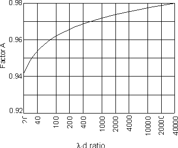
It is found that the antenna end effect increases with frequency and it also varies with different installations. Wire diameter also has a marked influence on this as shown in the diagram.
For a half wave dipole the length for a wave travelling in free space is calculated and this is multiplied by a factor "A". Typically it is between 0.96 and 0.98 and is mainly dependent upon the ratio of the length of the antenna to the thickness of the wire or tube used as the element. Its value can be approximated from the graph:

As a further complication, the supporting insulators, feed systems, and other surrounding objects, such as the earth, buildings, trees, etc have a noticeable effect upon the electrical length. This may even exceed the variation in length caused by practical variations in conductor diameter.
This makes an accurate length calculation difficult if not impossible to make under practical conditions. Accordingly, it is usual practice to determine the most likely length for the antenna, cut it a little longer than is expected and then check the characteristics of the antenna experimentally, altering the physical length as necessary.
Whilst most dipole antennas will be able to operate satisfactorily in most cases wth little or no adjustment, beng prepared to adjust the length slightly will help improve the performance and ensure that it is operating as effectively as possible in the given location.
Dipole length formula
It is quite easy to calculate the length of a half wave dipole using the simple formulae given below. Two versions are given for this length calculation – one using the length in metres and the other for the length in inches.
Often a formula for the length of a dipole in feet is seen as 468 / frequency. This can be derived by taking the figure of 492 seen in the formula above and multiplying it by the typical A or end effect factor of 0.95.
The actual figure derived is 467.48, but this is close enough for most applications, especially as the other factors including nearby objects, etc have a significant effect on the length.
The calculations from these formulas give a good starting point for determining the length of a dipole antenna. However factors like the proximity of the ground and other nearby objects as mentioned above also have a significant impact on the length and it is not easy to determine these beforehand.
Accordingly it is always best to make any prototype antenna slightly longer than the calculations might indicate and then shorten the antenna, measuring its performance each time. In this way the optimum performance can be obtained for that antenna.
It is best to trim the antenna length in small steps because the wire or tube cannot be replaced very easily once it has been removed.Computer simulation programmes are normally able to calculate the length of a dipole very accurately, provided that all the variables and elements that affect the operation of the dipole can be entered accurately so that the simulation is realistic and therefore accurate. The major problem is normally being able to enter the real-life environmental data accurately to enable a realistic simulation to be undertaken.
Antenna lengths for popular ham radio bands
Dipole antennas are used in many areas and applications. One of the main areas where home built antennas are required is within ham radio. Wire dipole antennas are often constructed and erected to provide an antenna for a particular band or sometimes bands.
In order to have an idea of the lengths required for half wave dipoles, the lengths widely used are given in the table.
| Approximate Lengths for Ham Band Dipole Antennas |
||
|---|---|---|
| Band (MHz) | Length (feet) | Length (metres) |
| 1.8 | 266 | 82.2 |
| 3.5 | 137 | 42.2 |
| 7.0 | 68.5 | 21.1 |
| 10.1 | 47.5 | 14.7 |
| 14.0 | 34.3 | 10.6 |
| 18.068 | 26.2 | 8.2 |
| 21.0 | 22.8 | 7.04 |
| 24.89 | 19.3 | 5.94 |
| 28.0 | 17.1 | 5.28 |
Note: The wire lengths are for the complete antenna and they will need to be cut in the centre for the feed point.
These lengths are widely used as the basis for a ham band dipole antenna. As already mentioned, the effect of the earth / height as well as nearby objects can alter the natural resonant length required, so a little experimentation is normally needed.
Tips for wire antennas
When cutting the wires to length for a wire dipole antenna, it is not only necessary to cut a little extra to enable the length to be trimmed, but it is also necessary to cut a little extra length extra to enable the wire of the antenna to be fixed tot he centre piece and also to the insulators, or whatever is used at either end.
This is because the active length of antenna does not include wire looped back for securing.
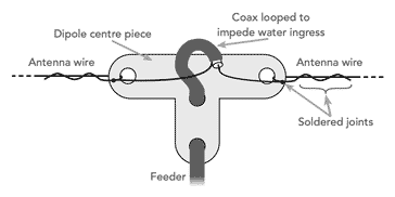
This is applicable for the centre piece as shown below. Whatever the form of the centre piece used, whether it is an insulator like that shown, or a balun - many baluns are designed to act as a dipole centre piece.

Strictly speaking a balun should be used but it is often omitted especially for receiving applications
While the dipole centre piece is important, the insulators at either end (or whatever fixing is used), will require additional length to be added.

Ensuring the leave sufficient additional wire for the fixing arrangements is essential to make sure that no wire needs to be aded, as this can be difficult to do satisfactorily once the antenna wire has been cut.
It is relatively easy to calculate the length of an antenna in theory. In practice, many other factors have a major impact on the length. Many antenna design programmes will help reduce the errors, but in practice, it is difficult to predict the effect of buildings, trees and the general topology of the earth and ow these factors will affect the antenna. It is always best to calculate the dipole length as best as possible and ten adjust for optimum performance in situ.
 Written by Ian Poole .
Experienced electronics engineer and author.
More Antenna & Propagation Topics:
EM waves
Radio propagation
Ionospheric propagation
Ground wave
Meteor scatter
Tropospheric propagation
Antenna basics
Cubical quad
Dipole
Discone
Ferrite rod
Log periodic antenna
Parabolic reflector antenna
Phased array antennas
Vertical antennas
Yagi
Antenna grounding
Installation guidelines
TV antennas
Coax cable
Waveguide
VSWR
Antenna baluns
MIMO
Return to Antennas & Propagation menu . . .


