
Home » Component data » Diode (PN junction) data » this page
1N5405 500V Rectifier Diode Data
Key data for the 1N5405 500V rectifier diode including key electrical parameters, performance, features, outline, package type and many other key datasheet details.
The 1N5405 is a general purpose plastic rectifier diode which has been designed for use in general purpose rectification of power supplies, inverters, converters and freewheeling diodes application.
The 1N5405 is one of a series of diodes, 1N5400 - 1N5408 for which the main difference is the reverse voltage capability.
Key details and performance parameters for the 1N5405 diode.
| 1N5405 diode datasheet parameters & data |
|
|---|---|
| Parameters | Details |
| Diode type | General purpose rectifier |
| Package type | DO201 |
| Repetitive peak reverse voltage, VRRM | 500 |
| DC blocking voltage, VR | 500 |
| RMS reverse voltage, VR(RMS) | 350 |
| Forward continuous current, IF | 3A |
| Average rectified current, IF | 3A |
| Non-repetitive forward surge current, IFSM | 200A |
| Power dissipation, PTOT | |
| Junction temperature (°C) | 150 |
| Forward voltage VF | 1.2V |
| Breakdown voltage VBR | |
| Reverse leakage IR | 5µA at 50V |
| Diode capacitance CD | 30 |
| Reverse recovery time | |
Outline & pinout:

Explanation of major diode parameters
| Parameter | Explanation |
|---|---|
| Repetitive peak reverse voltage, VRRM | This is the maximum value of the short period peak reverse voltage that can be sustained. |
| Working peak reverse voltage, VRWM | This is the maximum value of the continuous reverse voltage that can be applied to the diode. |
| DC blocking voltage, VR | This is the maximum reverse DC voltage that should be applied across the diode. |
| RMS reverse voltage, VR(RMS) | As many AC waveforms are quoted in RMS, this is the maximum reverse voltage that can be sustained where the voltage is expressed in terms of its RMS value. |
| Forward continuous current, IF | This is the maximum forward current that can be sustained by the diode. |
| Average rectified current, IF | This is the maximum average current value that can be handled by the diode. The parameter often states the load as this will affect the operation of the diode. |
| Non-repetitive forward surge current, IFSM | This is the maximum surge current that can be handled - it should only be present for a short time. |
| Parameter | Explanation |
|---|---|
| Power dissipation, PTOT | The maximum power dissipation that can be sustained within the device. |
| Junction temperature (°C) | This is the maximum temperature of the PN junction that can be sustained. Remember that the junction temperature can be much higher than the ambient temperature of the equipment. |
| Forward voltage VF | This parameter gives the forward voltage drop for a particular current passed through the diode. |
| Breakdown voltage VBR | This is the minimum voltage at which the diode may breakdown. If the current is not limited it will lead to the destruction of the device. |
| Leakage current IR | This is the current that flows under stated conditions when the diode is reverse biassed. |
| Diode capacitance CD | The diode capacitance, CD may also be referred to as the junction capacitance, CJ. All diodes have a certain capacitance across the PN junction. The value will be stated for a given reverse voltage. |
| Reverse recovery time | If a diode is initially driven in forward bias, and the polarity suddenly switches to reverse bias, the diode will still remain conducting for some time. The reverse recovery time is the time required for conduction to settle into the reverse bias state. |
These are the main operational amplifier parameters that have been included in our list. There are others, but these help quantify the main elements of the performance of the regulator, but are normally deemed to be less important.
Please note, that the data given is the best estimate we can give within a tabulated summary of this nature. Parameters also vary between manufacturers. Electronics Notes cannot accept any responsibility for errors, inaccuracies, etc, although we do endevaour to ensure the data is as accurate as possible.
Notes and supplementary information
• Availability & sources
The 1N5405 is available from a number of stockists and electronic component distributors many of which are given in the table below.
1N5405 Component Distributor, Stock and Pricing
• Further details
The 1N5405 can be used in a large number of different applications, especially as it has a 3 amp current capability.
As this device is so similar to other diodes in the series, it can be used to replace diodes such as the 1N5400, . . . 1N5404 which have lower voltage ratings. As all the ratings apart from the reverse voltage are the same, it is possible to use the 1N5405 to replace the lower voltage ones.
The 1N5405 is ideal for use as a rectifier diode in power supplies, inverters, converters and as well as in many other areas where high current capacity discrete diode many be required.
It can also be used to provide reverse polarity protection. To achieve this, the diode is placed in the supply line to prevent damage should the equipment be connected with the incorrect polarity. However there will be a voltage drop of possibly a volt or more dependent upon the current as a result of the forward drop across te diode.
• Reverse voltage ratings
When designing a circuit using rectifier diodes, it's very important to understand the reverse voltage that the diode will experience and what it can withstand.
It is important to ensure that the circuit has a sufficient capability to withstand the voltages it might experience.
The reverse voltage, VR depends not only on the voltages present within the circuit, but also the circuit configuration used.
The summary below provides a useful insight into what might be required.
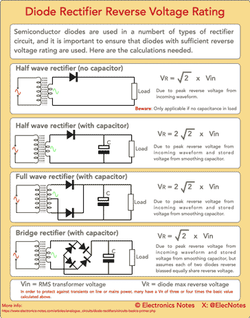
Click on image for the infographic
It is also worth remembering that the rating for the diode should also include a general margin so that it is not run at the top of its rating - often a figure of 60 - 70% is a standard for industry.
In addition to this it is also necessary for the diode to accommodate any transients that may be encountered. These often occur when systems are connected mains of line power. Any lightning or switching spikes can propagate along the power lines and appear at the input of equipment.
With a reverse voltage rating of 500V, the 1N5405 can be used in a variety of circuits where substantial voltages are present, making it a very useful device.
 Written by Ian Poole .
Experienced electronics engineer and author.
Return to Component Data menu . . .

