Exploring Electrolytic Capacitors - all the essential information
Understand the essentials of electrolytic capacitors, discover their benefits & understand how they can be used to provide high levels of capacitance with high reliability with our top tips.
Home » Electronic components » this page
Capacitor Tutorial Includes:
Capacitor uses
Capacitor types
Electrolytic capacitor
Ceramic capacitor
Ceramic vs electrolytic
Tantalum capacitor
Film capacitors
Silver mica capacitor
Super capacitor
Supercapacitor vs batteries
Surface mount capacitors
Specifications & parameters
How to buy capacitors - hints & tips
Capacitor codes & markings
Conversion table
The electrolytic capacitor is one of the mainstays of the capacitor industry being used in vast quantities both as a leaded device or an SMD.
The electrolytic capacitor is the most popular leaded type for values greater than about 1 µF, having the one of the highest levels of capacitance for a given volume.
Aluminium electrolytic capacitors have been in use for many years - in this way they have become a regular component in many designs.
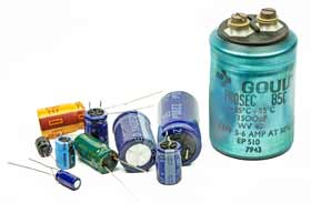
Electrolytic capacitors are widely used as leaded components, often being found in applications from power supplies to audio where leaded devices can be used. Initially aluminium electrolytic capacitors were not popular in surface mount technology format because of the levels of heat experienced during soldering could damage them. Now with more development, surface mount electrolytic capacitors are widely used and provide good levels of reliability.
Video: Understanding Electrolytic Capacitors
Electrolytic capacitor early development
The electrolytic capacitor has been in use for many years. Its early development and history can be traced back to the very early days or radio around the time when the first broadcasts of entertainment were being made.
At the time, valve wireless sets were very expensive, and they had to run from batteries. However with the development of the indirectly heated valve or vacuum tube it became possible to use AC mains power.
While it was fine for the heaters to run from an AC supply, the anode supply needed to be rectified and smoothed to prevent mains hum appearing on the audio.
In order to be able to use a capacitor that was not too large Julius Lilienfield who was heavily involved in developing wireless sets for domestic use was able to develop the electrolytic capacitor, allowing a component with sufficiently high capacitance but reasonable size to be used in the wireless sets of the day.
Electrolytic capacitor symbols
The electrolytic capacitor is a form of polarised capacitor. The electrolytic circuit symbol indicates the polarity as it is essential to ensure that the capacitor is fitted into the circuit correctly and is not reverse biased.

There is a variety of schematic symbols used for electrolytic capacitors. The first one '1' is the version that tends to be used in European circuit diagrams, while '2' is used in many US schematics, and '3' may be seen on some older schematics. Some schematic diagrams do not print the "+" adjacent to the symbol where it is already obvious which plate is which.
Electrolytic capacitor technology
As the name indicates, the electrolytic capacitor uses an electrolyte (an ionic conducting liquid) as one of its plates to achieve a larger capacitance per unit volume than other types.
The capacitors are able to increase the capacitance in a number of ways: increasing the dielectric constant; increasing the electrode surface area; and by decreasing the distance between the electrodes.
Electrolytic capacitors use the high dielectric constant of the aluminium oxide layer on the plate of the capacitor which averages between 7 and 8. This is greater than other dielectrics such as mylar which has a dielectric constant of 3 and mica of around 6 - 8.
In addition to this, the effective surface area within the capacitors is increased by a factor of up to 120 by roughening the surface of the high-purity aluminium foil. This is one of the keys to producing very high levels of capacitance.
Electrolytic capacitor construction
This type of capacitor is constructed using two thin films of aluminium foil, one layer being covered with an oxide layer as an insulator. The use of the aluminium foil give rise to the fact that the capacitor is often referred to as the aluminium electrolytic capacitor.
An electrolyte-soaked paper sheet is placed between them and then the two plates are wound around on one another and then placed into a can.
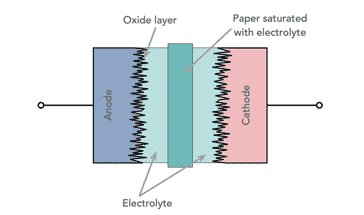
In the manufacture of the aluminium electrolytic capacitor, one of the first stages is to etch the foils to make them rougher to increase the surface area and hence the capacitance level that can be gained in a given area.
The next process is to form the anode. This entails chemically growing a thin layer of aluminium oxide, Al2O3 onto the anode foil making it different from the cathode.
The capacitor element itself is wound on a winding machine. The four separate layers: the formed anode foil; paper separator, cathode foil; and paper separator are all brought in and wound together. The paper separators prevent the two electrodes from touching and shorting.

When the assembly has been wound, it is taped to prevent unwinding.
Once the capacitor is wound, it is impregnated with the electrolyte. This may be done by immersion and under pressure.
The electrolyte used in aluminium electrolytic capacitors is a formulation developed to provide the required properties for the capacitor - voltage rating, operating temperature range and the like. It primarily consists of solvent and a salt (required to provide the electrical conduction). Common solvents include ethylene glycol, and common salt include ammonium borate and other ammonium salts.
Once this is complete the capacitor is placed into a can which is sealed to prevent evaporation of the electrolyte.
Main properties
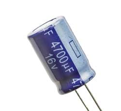
Aluminium electrolytic capacitors provide a much higher level of capacitance for a given volume than most ceramic capacitors. This means that high value electrolytic capacitors can be relatively small. This is a significant advantage in many instances.
Electrolytic capacitors are polarised, i.e. they can only be placed one way round in the circuit. If they are connected incorrectly they can be damaged, and in some extreme instances they can explode. Care should also be taken not to exceed the rated working voltage. Normally they should be operated well below this value.
The electrolytic capacitor has a wide tolerance. Typically the value of the component may be stated with a tolerance of -50% +100%. Despite this they are widely used in audio applications as coupling capacitors, and in smoothing applications for power supplies. They do not operate well at high frequencies and are typically not used for frequencies above 50 - 100 kHz.
Electrical parameters
There are a number of parameters of importance beyond the basic capacitance and capacitive reactance when using electrolytic capacitors. When designing circuits using electrolytic capacitors it is necessary to take these additional parameters into consideration for some designs, and to be aware of them when using electrolytic capacitors.
- Tolerance: Electrolytic capacitors have a very wide tolerance. Often capacitors may be quoted as -20% and +80%. This is not normally a problem in applications such as decoupling or power supply smoothing, etc. However they should not be used in circuits where the exact value is of importance.
- ESR Equivalent series resistance: Electrolytic capacitors are often used in circuits where current levels are relatively high. Also under some circumstances and current sourced from them needs to have a low source impedance, for example when the capacitor is being used in a power supply circuit as a reservoir capacitor. Under these conditions it is necessary to consult the manufacturers datasheets to discover whether the electrolytic capacitor chosen will meet the requirements for the circuit. If the ESR is high, then it will not be able to deliver the required amount of current in the circuit, without a voltage drop resulting from the ESR which will be seen as a source resistance.
- Frequency response: One of the problems with electrolytic capacitors is that they have a limited frequency response. It is found that their ESR rises with frequency and this generally limits their use to frequencies below about 100 kHz. This is particularly true for large capacitors, and even the smaller electrolytic capacitors should not be relied upon at high frequencies. To gain exact details it is necessary to consult the manufacturers data for a given part.
- Leakage: Although electrolytic capacitors have much higher levels of capacitance for a given volume than most other capacitor technologies, they can also have a higher level of leakage. This is not a problem for most applications, such as when they are used in power supplies. However under some circumstances they are not suitable. For example they should not be used around the input circuitry of an operational amplifier. Here even a small amount of leakage can cause problems because of the high input impedance levels of the op-amp. It is also worth noting that the levels of leakage are considerably higher in the reverse direction.
- Ripple current: When using electrolytic capacitors in high current applications such as the reservoir capacitor of a power supply, it is necessary to consider the ripple current it is likely to experience. Capacitors have a maximum ripple current they can supply. Above this they can become too hot which will reduce their life. In extreme cases it can cause the capacitor to fail. Accordingly it is necessary to calculate the expected ripple current and check that it is within the manufacturers maximum ratings.
Electrolytic capacitor markings
For the leaded versions of electrolytic capacitors, there is normally space for the various parameters to be placed onto the can. The markings commonly provide information about their capacitance value, working voltage, temperature range and possibly other parameters.
Video: Understanding Aluminium Electrolytic Capacitor Markings & Codes
It is often very important to understand the specifications for a capacitor before putting one into as a new component or replacement. Understanding the markings and codes youa re likely to find can be an essential skill for anyone involved in electronic circuit design, maintenance repair, or whatever.
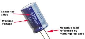
Some large capacitors intended for smoothing applications in power supplies may also carry further information. One particularly important parameter is the ripple current. If too much current is expected fromth e capacitor, it may heat up unduly and fail.
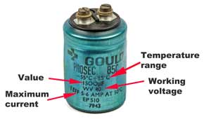
For SMD capacitors space is limited, so details are limited and may only contain the basic information.
Electrolytic SMD capacitors
Electrolytic capacitors are now being used increasingly in designs that are manufactured using surface mount technology, SMT. Their very high levels of capacitance combined with their low cost make them particularly useful in many areas.
Originally they were not used in particularly high quantities because they were not able to withstand some of the soldering processes. Now improved capacitor design along with the use of reflow techniques instead of wave soldering enables electrolytic capacitors to be used more widely in surface mount format.
Often surface mount device, SMD versions of electrolytic capacitors are marked with the value and working voltage. There are two basic methods used. One is to include their value in microfarads (µF), and another is to use a code.
Using the first method a marking of 33 6V would indicate a 33 µF capacitor with a working voltage of 6 volts.
An alternative code system employs a letter followed by three figures. The letter indicates the working voltage as defined in the table below and the three figures indicate the capacitance on picofarads. As with many other marking systems the first two figures give the significant figures and the third, the multiplier.
In this case a marking of G106 would indicate a working voltage of 4 volts and a capacitance of 10 times 10^6 picofarads. This works out to be 10µF.
| SMD Electrolytic Capacitor Voltage Codes | |
|---|---|
| Letter | Voltage |
| e | 2.5 |
| G | 4 |
| J | 6.3 |
| A | 10 |
| C | 16 |
| D | 20 |
| E | 25 |
| V | 35 |
| H | 50 |
Top tips for using aluminium electrolytic capacitors
Electrolytic capacitor can have a bad name for reliability, but if used well, they can provide very reliable service. If soem top tips are followed, then they can be a very good choice for a capacitor.
Video: 5 Tips for Using Electrolytic Capacitors in Your Circuit Designs
Aluminium electrolytic capacitors do degrade with time. Many electrolytics have a vent for allowing excess gasses to escape. This escape can result in the electrolyte drying out and the performance of the capacitor falling.
Also if aluminium electrolytic capacitors are left for a few years, then the oxide layer on the anode can dissipate. When this happens the capacitor needs to be repolarised. This can be done by applying a current limited voltage to the capacitor. Initially the leakage current across the capacitor will be relatively high and then it will fall as the oxide layer forms.
It is also wise to take precautions to prolong the life of the capacitor, and ensure the ebst overall reliability. Below are our golden tips to maximise the life of an aluminium electrolytic capacitor and ensure the best reliability:
- Understand the essentials of electrolytic capacitors, discover their benefits & understand how they can be used to provide high levels of capacitance with high reliability with our top tips.
- Run within its voltage limits: It is always wise to run any component with a good margin below the maximum ratings. Many companies state in their design rules that for electrolytic capacitors, they should only be run at about 50% of their maximum ratings to ensure optimum reliability. If the maximum limits are exceeded then leakage current levels will rise and there is the possibility of localised breakdown leading to an explosive failure of the component.
- Keep within its current rating: In many applications an electrolytic capacitor will be required to provide high levels of ripple current. This is to be expected in applications like being used as a smoothing capacitor in a power supply. Ii is imperative to ensure that the capacitor can withstand the current being required from it. Check that the capacitor is operating within its current limits and is not becoming too warm in operation.
- Never reverse bias the capacitor: When run under a reverse bias, the leakage levels will be very much higher than in the forward direction. Again this can lead to catastrophic breakdown and failure.
- Keep temperatures down: Heat shortens the life of any aluminium electrolytic capacitor. A good rule of thumb is that every 10°C over 85°C will halve the life expectancy of the component.
Only for lower frequencies: Electrolytic capacitors are not good when used at higher frequencies. Typically they are limited to frequencies up to a maximum of around 100kHz.
These tips will help ensure that the best performance is obtained when an electrolytic capacitor is used in an electronic circuit design, and also that they are chosen when they are the best option for the given situation.
Reforming aluminium electrolytic capacitors
It may be necessary to re-form electrolytic capacitors that have not been used for six months or more. The electrolytic action tends to remove the oxide layer from the anode and this needs to be re-formed.
Under these circumstances it is not wise to apply the full voltage as the leakage current will be high and may lead to large amounts of heat being dissipated in the capacitor which can in some instances bring about its destruction.
To reform the capacitor, the normal method is to apply the working voltage for the capacitor through a resistor of around 1.5 k ohms, or possibly less for lower voltage capacitors. (NB ensure that it has sufficient power rating to handle the capacitor in question).
This should be applied for an hour or more until the leakage current drops to an acceptable value and the voltage directly on the capacitor reaches the applied value, i.e. virtually no current is flowing through the resistor.
This voltage should then be continued to be applied for a further hour. The capacitor can then be slowly discharged through a suitable resistor so that the retained charge does not cause damage. Once reformed take care when using the capacitor to make sure that it has been fully reformed and is able to function correctly.
Electrolytic capacitor summary
| Aluminium Electrolytic Capacitor Summary | |
|---|---|
| Parameter | Details |
| Typical capacitance ranges | 1µF to 47 000µF |
| Rated voltage availability | From around 2.5V upwards - some specialised ones can have voltages of 350V and more. |
| Advantages | High capacitance per volume compared to most other types, relatively cheap when compared to other types of similar value. |
| Disadvantages | High leakage currents, wide value tolerances, poor equivalent series resistance; limited lifetime. |
 Written by Ian Poole .
Experienced electronics engineer and author.
More Electronic Components:
Batteries
Capacitors
Connectors
ADC
DAC
Diodes
FET
Inductors
Memory types
Phototransistor
Quartz crystals
Relays
Resistors
RF connectors
Switches
Surface mount technology
Thyristor
Transformers
Transistor
Unijunction
Valves / Tubes
Return to Components menu . . .


