Construction & Operation of the Coherer
Details of how the coherer works, the coherer operation and details of its construction and how it was made.
Radio Coherer History Includes:
Coherer history & basics
Coherer construction & operation
Decoherer
The construction of the coherer was the subject of much experimentation. Often details of the construction of various coherers were kept secret from the competition because the operation of the coherer gave the key to success or failure of a radio communications system.
A coherer that operated well would provide a significant advantage in any trials as the detector, of which a cohere was a form, was often the limiting element in the successful transmission and reception of a signal.
Basis of operation of the coherer
The coherer was a form of detector whose operation was applicable to the very early radio transmissions that were being used at the end of the nineteenth and beginning of the twentieth centuries.
These transmissions used signals generated by a continuous spark which was turned on and off, or keyed to give the Morse code characters required. In this way, the operation of the early detectors such as the coherer only needed to detect the presence or absence of a signal.
There are two types of coherer, and the operation of them is slightly different. The two types are:
- Branly coherer
- Imperfect junction coherer
The basis of the coherer operation and construction is different for both types. The Branly coherer operation is what may be termed as the basic coherer operation and it will be covered first.
Branly coherer operation & construction
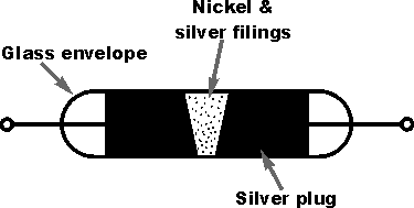
This type of coherer was the first to be invented and used and was used by many companies for inclusion in their radio communications systems. Typically it consists of a glass tube containing two electrodes and some metal filings of power. Often a mixture nickel and silver in equal parts was used.
The typical construction was basically of the type used by Marconi shown below.

The coherer was constructed using a glass tube that was sometimes evacuated. The two electrodes within the glass tube were also brought close to each other. In the case of the Marconi coherer, this was to within a couple of millimetres of one another.
When radio signal impacted on the coherer, the particles would cohere or join up and stick together. The mechanism behind this is a micro-weld phenomenon. This is caused by the radio frequency current that is caused to flow across the small contact area between the individual particles.
Imperfect junction coherer
The second type of coherer is known as the imperfect junction coherer.
There are several variations to the imperfect junction coherer which is quite different to the Branly coherer. Essentially the imperfect junction coherer consists of a small metallic cup which contains a pool of mercury. This is covered by a very thin insulating film of oil. A small iron disc is then suspended above the surface of the oil film.
An adjusting screw is then used to lower the disc until its lower edge just touches the mercury with a pressure small enough not to puncture the film of oil.
Its principle of operation is not well understood but detection occurs when the radio frequency signal breaks down the insulating film of oil, allowing the device to conduct. This, in turn is made to operate the receiving sounder. The imperfect junction coherer is self-restoring and needs no decohering.
The disadvantage of the imperfect junction coherer is that it is very delicate to set up.
Coherer circuits
The radio antenna and earth were applied directly across the contacts of the coherer so that the radio signal would be developed across the electrodes. When the radio signal was received, the coherer would become conductive.
The electrodes for the coherer were also attached to a second DC circuit. This was decoupled using an inductor. This circuit would then either be presented to a set of headphones, in which a click would be heard, or it could be used to drive an inker to record the signal as shown below.

Disadvantages of coherers
The coherer was never a very satisfactory form of detector. It suffered from several disadvantages:
- Insensitive: The signal level had to be high to cause the particles in the device to cohere.
- Not resilient to interference: All forms of signal would cause the coherer to be activated. It was therefore difficult to operate under noisy conditions, especially when levels of static were high.
- Expensive: With all the materials used and the need for specialised glass tubes, coheres were expensive to produce.
- Only able to detect Morse signals: With the introduction of amplitude modulated signals for sound transmissions it was not possible to use the coherer as its mode of operation was not suitable for this.
In view of its limitations and the fact that better detectors were introduced, the coherer fell into disuse for radio communications systems after about 1907.
 Written by Ian Poole .
Experienced electronics engineer and author.
More History:
Radio history timeline
History of the radio
Ham radio history
Coherer
Crystal radio
Magnetic detector
Spark transmitter
Morse telegraph
Valve / tube history
PN junction diode invention
Transistor
Integrated circuit
Quartz crystals
Classic radios
Mobile telecoms history
Vintage mobile phones
Return to History menu . . .


