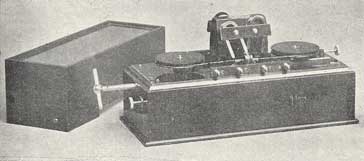
Magnetic Detector Operation & Construction
Details of the operation and construction of the magnetic detector used as an early detector for radio signals.
Magnetic Detector History Includes:
Magnetic detector
Operation & construction
As the name implies the magnetic detector or Maggie used magnetic effects to detect wireless signals.
It took some years before its operation was fully understood. Nevertheless construction of magnetic detectors was optimised considerably, although mainly by trial error.
Much of this improvement in the construction and operation of the magnetic detector was undertaken by Marconi. He saw it as a way to further his business and improve the performance of his wireless systems to gain a competitive edge over other suppliers.

Magnetic detector operation concept
The operation of the magnetic detector is based on the effects that electromagnetic radiation has on ferromagnetic materials.
The basic magnetic detector normally comprised of a band of iron wires that moved continuously around two ebonite pulleys. The band passed through the centre of two concentric coils of wire. The first coil often referred to as the primary was connected to the antenna circuit. The second coil, i.e. the secondary was connected to a telephone earpiece allowing the signals to be heard.

View from top
The magnetic detector operation is based around the fact that the magnetisation of the soft iron wire has a certain level of hysteresis.
The permanent magnets shown on the diagram of the magnetic detector are arranged to create two opposing fields but directed towards the centre of the coils.
These permanent magnets serve to magnetise the iron band as it moves through the inductor – first in one direction as it enters the coil and then the other as it leaves the coil.
As a result of the hysteresis in the magnetisation process of the soft iron band in the detector, a certain threshold magnetic field is required to reverse the magnetization. As a result, the magnetization in the moving wires does not reverse in the center of the detector coil where the field reverses, but some way toward the departing side of the wires.
In the absence of an incoming radio signal the location where the magnetisation of the moving band reverses is stationary with respect to the coil. As a result of this there is no flux change and no voltage is induced in the pickup or secondary coil in the magnetic detector.
When a signal is received and enters the magnetic detector coil, the operation changes. The rapidly reversing magnetic field from the coil exceeds the level required to overcome the hysteresis of the iron. This causes the magnetisation change to suddenly move up the wire to the center, between the magnets, where the field reverses.
The movement of the position of the magnetization change has an effect similar to suddenly moving a magnet into the coil. It causes the magnetic flux through the secondary coil to change, inducing a current pulse. As the secondary coil is connected to headphones, the current pulse can be heard as a sound.
As the transmission from a spark transmitter consists of a series of damped impulse waves, the sound heard in the headphones was generally a buzz, or sometimes even a more musical tone.
As described by S Bottone in his early book of 1910 entitled Wireless Telegraphy and Hertzian Waves:- “On placing the ear to the telephone, a distinctive ‘click’ is heard at every impact of the wireless wave on the aerial.”

Magnetic detector circuit
The magnetic detector essentially consists of a low impedance input or primary coil, typically wound on a hollow glass tube. One end is connected to the antenna, and the other end to ground.
A second coil is wound on the glass tube and this forms a step up transformer as it has more turns on the coil than the primary. It forms a step up transformer enabling this winding to be connected to a set of high impedance headphones.
The key to the operation of the magnetic detector is the band of soft iron that moves through the glass tube. A pair of permanent magnets are arranged close to the coils to provide a magnetic field in the vicinity.
When a signal arrives at the input inductor there is a sudden change in the level of magnetism which in turn energises L2. The effect of the movement of the band of soft iron means that the earphones are energised and a click is heard.
The magnetic detector was able to detect spark transmissions that were used in that time; it was not able to detect signals that were an interrupted continuous wave, like those from valve transmitters.
The improved sensitivity over coherers meant that the magnetic detector was widely used in the days of spark transmissions up to the early 1910s when valve and other types of transmitters used continuous wave signals.
 Written by Ian Poole .
Experienced electronics engineer and author.
More History:
Radio history timeline
History of the radio
Ham radio history
Coherer
Crystal radio
Magnetic detector
Spark transmitter
Morse telegraph
Valve / tube history
PN junction diode invention
Transistor
Integrated circuit
Quartz crystals
Classic radios
Mobile telecoms history
Vintage mobile phones
Return to History menu . . .


