Quartz crystal band pass filters
The basics of the different types of crystal filter that can be used in radio communications receivers including the single crystal filter, half lattice crystal filter, and the ladder crystal filter.
Home » Radio & RF technology » this page
RF Filters Includes:
RF filters - the basics
Filter specifications
RF filter design basics
High & low pass filter design
Constant-k filter
Butterworth filter
Chebychev filter
Bessel filter
Elliptical filter
Crystal filter
Crystal filters are widely used in many applications including radio receivers as well as many other radio communications applications. The very high level of Q makes the quartz crystal resonators they use makes them ideal for use as the primary band pass RF filter in high performance radio communications receivers. As a result of this there are a number of circuits that have been used to provide the required level of selectivity and performance over the years. These include the single crystal filter, the half lattice crystal filter and the ladder filter.
Single crystal filter
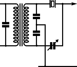
The simplest crystal filter employs a single crystal. This type of RF filter was developed in the 1930s and was used in early receivers dating from before the 1960s but is rarely used today. Although it employs the very high Q of the crystal, its response is asymmetric and it is too narrow for most applications, having a bandwidth of a hundred Hz or less.
In the circuit there is a variable capacitor that is used to compensate for the parasitic capacitance in the crystal. This capacitor was normally included as a front panel control.

Half lattice crystal filter
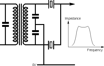
This form of band pass RF filter provided a significant improvement in performance over the single. In this configuration the parasitic capacitances of each of the crystals cancel each other out and enable the circuit to operate satisfactorily. By adopting a slightly different frequency for the crystals, a wider bandwidth is obtained. However the slope response outside the required pass band falls away quickly, enabling high levels of out of band rejection to be obtained. Typically the parallel resonant frequency of one crystal is designed to be equal to the series resonant frequency of the other.
Despite the fact that the half lattice crystal filter can offer a much flatter in-band response there is still some ripple. This results from the fact that the two crystals have different resonant frequencies. The response has a small peak at either side of the centre frequency and a small dip in the middle. As a rough rule of thumb it is found that the 3 dB bandwidth of the RF filter is about 1.5 times the frequency difference between the two resonant frequencies. It is also found that for optimum performance the matching of the filter is very important. To achieve this, matching resistors are often placed on the input and output. If the filter is not properly matched then it is found that there will be more in-band ripple and the ultimate rejection may not be as good.

A two pole filter (i.e. one with two crystals) is not normally adequate to meet many requirements. The shape factor can be greatly improved by adding further sections. Typically ultimate rejections of 70 dB and more are required in a receiver. As a rough guide a two pole filter will generally give a rejection of around 20 dB; a four pole filter, 50 dB; a six pole filter, 70 dB; and an eight pole one 90 dB.
Crystal ladder filter
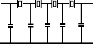
For many years the half lattice filter was possibly the most popular format used for crystal filters. More recently the ladder topology has gained considerable acceptance. In this form of crystal pass band filter all the resonators have the same frequency, and the inter-resonator coupling is provided by the capacitors placed between the resonators with the other termination connected to earth.

Quartz crystal filter design parameters
When a quartz crystal filter is designed factors such as the input and output impedance as well as bandwidth, crystal Q and many other factors need to be taken into account.
Some of the chief factors are obviously the bandwidth, shape fact, and ultimate cutoff. Although it is very much a simplification, these factors are dependent upon the number of poles (equivalent to the number of crystals), their Q value, and their individual frequencies.
Further factors such as the maximum bandwidth that can be achieved is controlled by the filter impedance and also the spurious responses that are present in the individual quartz crystal elements. The location of the important responses for quartz crystal filters can be controlled by the size of the plates deposited onto the crystals. By making them smaller the responses also become less critical. The down side of this is that the impedance of the overall quartz crystal filter rises. This means that the quartz crystal filter will need impedance transformers at the input and the output. This obviously needs to be avoided if at all possible, but for wide band filters it is often the only option.
Crystal filters are widely used in many radio communications receiver applications. Here these filters are able to provide very high levels of performance and at a cost which is very reasonable for the performance that is given. These RF filters may be made in a variety of formats according to the applications and the performance needed. While these RF filters can be made from discrete components, ready manufactured crystal filters are normally bought, either off the shelf, of made to a given specification.
 Written by Ian Poole .
Experienced electronics engineer and author.
More Essential Radio Topics:
Radio Signals
Modulation types & techniques
Amplitude modulation
Frequency modulation
OFDM
RF mixing
Phase locked loops
Frequency synthesizers
Passive intermodulation
RF attenuators
RF filters
RF circulator
Radio receiver types
Superhet radio
Receiver selectivity
Receiver sensitivity
Receiver strong signal handling
Receiver dynamic range
Return to Radio topics menu . . .


