Superheterodyne Receiver Image Response & Specification
The superheterodyne radio receiver has an issue referred to as the image: there are two frequencies that can mix with the local oscillator to enter the IF.
Home » Radio & RF technology » this page
Superhet Radio Tutorial Includes:
Superhet radio
Superhet theory
Image response
Block diagram / overall receiver
Design evolution
Double & multi-conversion superhet
Specifications
See also: Radio types
The basic concept of the superheterodyne receiver appears to be fine, but there is a problem. There are two signals that can enter the Intermediate frequency stages.
The unwanted signal that can enter the intermediate frequency stages is known as the image signal and reducing the image response is an important aspect of the RF design of the receiver.
If the image response is not suppressed sufficiently, then image signals, i.e. signals on the image frequency can be received and interfere with the wanted signal on the required channel.
Although some level of image response will always be present, if only to a small degree, the image performance is particularly important for professional radio communications applications: two way radio communications transceivers, professional radio communications receivers and the like.
Video: Superhet Radio Image
Concept of the superheterodyne radio image
The image response in a superhet radio arises because there are two frequencies where signals can mix with the local oscillator to give an output on the intermediate frequency.
As a result of the mixing process, signals can enter the receiver and be converted down to the intermediate frequency if they are on either the local oscillator frequency plus that of the IF, or the local oscillator frequency minus that of the IF.
This can be expressed mathematically as:
It can also be seen from this that the two signals that can be received are spaced apart by a frequency equal to twice that of the IF.
It is often helpful to see how this works out by adding some real figures to an example.
With the local oscillator set to 0.75 MHz and with an IF of 0.25 MHz, it can be seen that a signal at 1.0 MHz mixes with the local oscillator to produce a signal at 0.25 MHz that will pass through the IF filter.
However if a signal at 0.5 MHz enters the mixer it produces two mix products, namely one at the sum frequency which is 1.25 MHz, whilst the difference frequency appears at 0.25 MHz. This would prove to be a problem because it is perfectly possible for two signals on completely different frequencies to enter the IF.
The unwanted frequency is known as the image frequency or image response. A signal that is received on this frequency is known as the image signal.
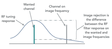
To overcome of the issue of the image response it is possible to place a tuned circuit before the mixer to prevent the signal entering the mixer, or more correctly reduce its level to acceptable value.

This RF tuning circuit does not need to be very sharp. It does not need to reject signals on adjacent channels, but instead it needs to reject signals on the image frequency. These will be separated from the wanted channel by a frequency equal to twice the IF. In other words with an IF at 0.25 MHz, the image will be 0.5 MHz away from the wanted frequency.
Superheterodyne receiver image
There are several facts about the superheterodyne receiver image response that can be summarised quite easily.
Image is twice the IF away from the wanted signal: Frequencies that enter the IF are spaced from the local oscillator by an amount equal to the intermediate frequency. Therefore if one frequency is LO + IF, the other one will be LO – IF. This means that the difference between the wanted signals and the image frequency is two times the IF, i.e. twice the intermediate frequency. It is for this reason high intermediate frequencies may be chosen as it improves the image performance.
Superheterodyne receiver image is twice the IF away from the wanted signal RF tuning: In order to ensure that the RF tuning does not introduce any undue signal reduction, and it ensures the image response is reduced by the maximum amount, it tunes in line with the local oscillator. Thus if the LO increases by 1 MHz then the RF tuning must increase by the same amount to ensure it tracks the received signal frequency correctly.
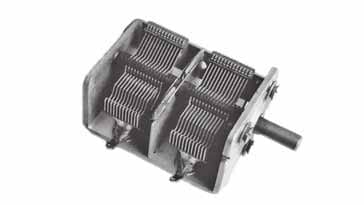
Early radio receivers used ganged tuning capacitors consisting of two sections. Attached to the same spindle the capacitance of each section changed by the same amount enabling the RF tuning to track at the same rate as the local oscillator.

A variable capacitor as used for tuning within radios It can be seen that the same spindle on the capacitor varies both sections of the capacitor and hence they will both vary at the same rate.
Modern radios using electronic forms of tuning using varactor diodes will also need to ensure that both the RF and local oscillator tune together so that they track and ensure the signals are received correctly.
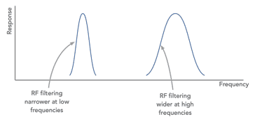
Image rejection degrades with increasing frequency : It is found that the image rejection of a radio receiver will degrade with increasing frequency. The reason for this is that the filter will have a level of Q that will be normally similar at all frequencies. This means that the bandwidth in terms of percentage of the frequency will remain similar, but in terms of the actual bandwidth in terms of frequency it will widen for increasing frequency.

The bandwidth of the RF filter will increase with increasing frequency thereby degrading the image performance As the difference between the wanted frequency and image frequency remain fixed, this means that the image performance will degrade with increasing frequency.
Image performance specification
In view of the importance of the image performance of a superheterodyne radio, this forms a key specification parameter for any radio in its data sheet. It will be particularly prominent in radios used for professional radio communications receiving applications. It is also important for the receiver sections of transceivers used for two way radio communications.
The image rejection of a radio receiver will be specified as the ratio in decibels between the receiver response for the wanted and image frequencies. This will be specified for a certain operating frequency because the image rejection will vary with frequency.

An example specification may be 60 dB at 30 MHz. This means that if signals of the same strength were present on the wanted frequency and the image frequency, then the image signal would be 60 dB lower than the wanted one. It will be found that radios used in professional radio applications will provide a better level of image rejection than this.
The frequency at which the measurement is made also has to be included. This is because the level of rejection will vary according to the frequency in use. Typically it gets worse as the received frequency increases because the percentage frequency difference between the wanted and image signals is smaller.
The superheterodyne receiver image response is a key performance parameter that is measured in receivers. It is possible to reduce any image signals by significant amounts in high performance receivers so that it does not cause any major problems. Low cost receivers normally have some problems although in recent years receiver image performance levels have improved significantly.
 Written by Ian Poole .
Experienced electronics engineer and author.
More Essential Radio Topics:
Radio Signals
Modulation types & techniques
Amplitude modulation
Frequency modulation
OFDM
RF mixing
Phase locked loops
Frequency synthesizers
Passive intermodulation
RF attenuators
RF filters
RF circulator
Radio receiver types
Superhet radio
Receiver selectivity
Receiver sensitivity
Receiver strong signal handling
Receiver dynamic range
Return to Radio topics menu . . .


