
Rhombic Wire Antenna
Terminating the remote end of a wire antenna will result on the major lobes of radiation being directed towards the termination and those facing away are reduced.
Home » Antennas & Propagation » this page
Long Wire / End Fed Wire Antenna Includes:
End fed / long wire antenna
Multiple wavelength long wire
End fed half wave antenna
W3EDP antenna
Random wire antenna
Terminated long wire antenna
V beam antenna (bidirectional)
Unidirectional V beam antenna
Rhombic antenna
One of the antennas that have been used in the past and to which many radio amateurs aspire is the rhombic antenna.
In many respects it can be seen as a development of the multi-wavelength long wire antenna which has processed to the end fed V beam and onto the rhombic.

The rhombic antenna has been used over many years, being used for HF telecommunications links when no other means were possible. It's also been widely used for HF broadcasting where a given target area and hence direction may be required.
It's also possible to make a much smaller version for VHF / UHF use, although designs are not widely seen.
The rhombic antenna is large, and not rotatable, and therefore it tended to be used for transmission and reception where a fixed direction is required, and where space for the antenna was not an issue.
The Rhombic Antenna: A Historical Perspective
The rhombic antenna was devised in 1931 by Edmond Bruce and Harald Friis. It quickly gained popularity in the early days of shortwave communication because of its effectiveness in long-distance point-to-point communication.
Prior to World War II, rhombic antennas were widely used by government agencies, military forces, and international broadcasters for reliable long-range communication.
It must be remembered that the Yagi had not been devised at this time and it was only during WW2 that the Yagi started to be used. As a result, antennas like the rhombic offered a very good solution for a directive antenna.
However, with more compact options like the Yagi and some other antennas being more widely available, the rhombic has fallen from the headlines today it is used less, although it still offers many advantages.
Rhombic antenna basics
The rhombic is easily recognisable in diagrammatic form by its rhombus or diamond shape - hence the name.
In essence this antenna is based around the end fed long wires and the V beam wire antennas. In fact it can be considered as two V beam antennas, one the mirror image of the other connected together at the open end.
There are two types of rhombic antenna:
Unterminated Rhombic: For this option, there are no terminating resistors at the remote end of the antenna - it is left open at the far end. This configuration provides a lower level of directionality, but the efficiency is higher because there is no power being dissipated in the terminating resistor.
Terminated Rhombic: For the terminated version of the rhombic antenna, a resistor is attached at its far end, absorbing any excess energy that might reflect back. This configuration offers even better directionality but reduces overall efficiency slightly.
The concept of the rhombic antenna is that the four sides of the diamond shape each have their own directive pattern. These combine together to give an overall directive pattern that is much sharper than the individual legs.
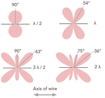
Normally each leg is longer than a wavelength and therefore the major radiation lobes start to move to align with the axis of the wire, making them directive in their own right.
As seen with any long wire antenna, the main lobes of the radiation pattern move towards the axis of the antenna as its length increases.
This characteristic is used by both the terminated and unterminated versions of the antenna. It is found that the overall antenna directional pattern makes use of this, and the individual patterns from the sections combine to give a single main lobe or lobes with a number of minor ones. The terminated antenna fires most of its radiation in one direction, whereas the unterminated one is bi-directional.

The diagram shows the angles within the antenna with the Greek letter Φ, this angle is normally referred to as the "tilt" angle.
It should be set to 90° minus the angle of maximum radiation for the length of the element.
By adjusting the tilt angle for the frequency, etc in use, the lobes of the individual wire lengths, l, can be made to align, and in this way give the maximum forward gain.
If they do not align optimally, then the directivity will not be as sharp and the gain will be somewhat less. That said, the antenna will still work satisfactorily over a relatively wide bandwidth giving a good level of gain.
Rhombic advantages & disadvantages
The rhombic antenna has many advantages in terms of its performance.
Simple Construction: Rhombic antennas are relatively easy to construct using readily available materials like wire, insulators, and support structures, although these may not always be straightforward, but the basic constructional concept is straightforward.
Low Maintenance: The simple design makes them reliable and requires minimal maintenance.
Broadband Operation: Their ability to operate effectively over a wide range of frequencies makes them suitable for a variety of communication needs.
Long-Distance Communication: With their good directionality and gain, rhombic antennas remain a viable option for long-distance shortwave communication.
However, the rhombic is not always the most suitable and has a number of disadvantages.
Size: One of the key issues with the rhombic antenna is its size. Each leg must be a few wavelengths long and this means that it is too large for many installations, especially those for most radio amateurs, etc.
Rotatability: The sheer size of a rhombic means that it cannot be rotated, at least for GHF antennas - if one was made for UHF, then this could most likely be rotated.
Rhombic antenna applications
The rhombic antenna is only used in a number of applications because of its size, but despite this it performs well where space is available.
There are a number of areas where it is and has been sued over the years, primarily for HF operation.
HF broadcasting: The rhombic antenna is used by many short wave broadcasters. As transmissions are often beamed at particular areas, this fits well with the way in which this antenna works.
HF point to point links: Where HF radio is used for communications between two fixed points, the rhombic is able to provide the performance often needed. This might be for long term government HF communications, or my commercial users where the locations are not changed.
Amateur radio: This type of antenna is often the dream of many radio amateurs, although very few possess the space for them.
VHF / UHF antenna: The shorter wavelength of antennas at this frequency mean that it has been used on some occasions as a rotatable antenna for operation at these frequencies. It has been considered as a TV antenna on occasions.
Although rhombic antennas are not widely used these days because of their size. However they can still be used in a limited number of situations where a fixed high gain antenna is needed.
 Written by Ian Poole .
Experienced electronics engineer and author.
More Antenna & Propagation Topics:
EM waves
Radio propagation
Ionospheric propagation
Ground wave
Meteor scatter
Tropospheric propagation
Antenna basics
Cubical quad
Dipole
Discone
Ferrite rod
Log periodic antenna
Parabolic reflector antenna
Phased array antennas
Vertical antennas
Yagi
Antenna grounding
Installation guidelines
TV antennas
Coax cable
Waveguide
VSWR
Antenna baluns
MIMO
Return to Antennas & Propagation menu . . .

