Terminated Long Wire Antenna Directivity Explained
Terminating the remote end of a wire antenna will result on the major lobes of radiation being directed towards the termination and those facing away are reduced.
Home » Antennas & Propagation » this page
Long Wire / End Fed Wire Antenna Includes:
End fed / long wire antenna
Multiple wavelength long wire
End fed half wave antenna
W3EDP antenna
Random wire antenna
Terminated long wire antenna
V beam antenna (bidirectional)
Unidirectional V beam antenna
Rhombic antenna
The concept of an end fed wire is a very familiar one, but less familiar is the concept of terminating the remote end so that, effectively both ends are terminated.
By terminating the remote end it means that one end is terminated by the load, i.e. transmitter or receiver, and the remote end is terminated by the resistor.
Terminating the remote end of the antenna means that the familiar directional pattern of the end fed wire is changed, retaining the lobes that are towards the termination and reducing those away from the termination.

The Essence of a Long Wire Antenna
At its core, a long wire antenna is a simple wire suspended in the air. Ideally, the length should be several wavelengths of the target frequency if an end fire effect is to be achieved. This basic design results in a number of lobes in the radiation pattern. This pattern is mirrored about a plane that is at right angles to the axis of the antenna.
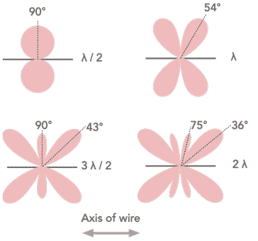
from these diagrams it can be seen that the lobes exist in both directions along the axis of the antenna.
However, it is often useful to reduce the number of lobes and have the main lobes aiming in one direction only as this can reduce the level of received interference, for example.
Termination: The Key to Directionality
It is found that by terminating the remote end of the long wire, it is possible to significantly alter the directional pattern of the antenna and make it unidirectional rather than bi-directional.
This can be achieved by terminating the remote end of the antenna: A resistor, typically with a specific resistance value, is attached to the end of the wire opposite the feedpoint (the point where the transmission line connects). This resistor "absorbs" any excess energy traveling down the wire, preventing it from radiating outwards.
Terminating the wire significantly alters the operation of the antenna:
Current Distribution: Without any termination, current flows freely along the entire length of the wire, and reflected back as standing waves are set up for both current and voltage. This results in a bidirectional radiation pattern.
However, termination reduces the standing wave pattern, ideally to zero and this alters the radiation pattern.
Interference and Cancellation: It is found that for an unterminated long wire antenna, the signal is radiated from the wire and as the phase of the radiated signal differs along the length of the wire, there are angles at which the signal reinforces and other angles at which is cancels. The same occurs for the terminated wire, except that the reinforcement takes place towards the direction of the termination.

The directionality of a terminated long wire antenna depends on several factors:
Length of the Wire: The length of the wire relative to the operating wavelength plays a crucial role. Longer wires provide better directivity because there are more wavelengths over which the reinforcement and cancellation can occur.
Termination Resistance: The chosen resistance value of the termination resistor affects the current distribution and ultimately the radiation pattern. The most directivity is obtained by matching the termination resistance to that of the antenna and in this way no standing waves are set up on the radiating portion of the antenna.
Height Above Ground: The height of the wire above the ground also influences the directivity. Higher installations typically offer better performance.
Benefits of Terminated Long Wire Antennas
The possibility of using a terminated long wire antenna may be limited by the actual length required. Typically these antennas need to be several wavelengths long and straight. This is likely to require a significant amount of space and this will limit their applicability.
These antennas are not rotatable and therefore, before considering their use it is necessary to look at their advantages.
Simple Construction: These antennas are relatively easy to build using readily available materials like wire and resistors.
Cost-Effective: The simple design makes them a budget-friendly option for both amateur radio enthusiasts and some commercial applications.
Directional Capability: The ability to focus the signal in a specific direction can be highly advantageous for long-distance communication or reducing interference.
Multi-Band Operation: A terminated long wire antennas can be used effectively across multiple frequencies, although the elvel of directivity does change as the frequency changes giving a different length in terms of the number of wavelengths .
Terminated long wire antennas offer a fascinating blend of simplicity and functionality. Their construction is relatively straightforward, although they do require a good amount of space.
However their simplicity, combined with their performance makes them a viable option for radio enthusiasts, broadcasters, and even the military in specific applications.
They have limitations, particularly at higher frequencies and with regards to tuning complexity, but their cost-effectiveness and directional capabilities continue to make them a relevant design in the ever-evolving world of radio communication.
 Written by Ian Poole .
Experienced electronics engineer and author.
More Antenna & Propagation Topics:
EM waves
Radio propagation
Ionospheric propagation
Ground wave
Meteor scatter
Tropospheric propagation
Antenna basics
Cubical quad
Dipole
Discone
Ferrite rod
Log periodic antenna
Parabolic reflector antenna
Phased array antennas
Vertical antennas
Yagi
Antenna grounding
Installation guidelines
TV antennas
Coax cable
Waveguide
VSWR
Antenna baluns
MIMO
Return to Antennas & Propagation menu . . .