Coax Impedance: Coaxial Cable Characteristic Impedance
The characteristic impedance of any coaxial cable is key to the selection of the required type. It is often the first consideration.
Home » Antennas & Propagation » this page
Coax Tutorial Includes:
Coax feeder
Coax specifications overview
Coax impedance
Coax loss / attenuation
Coax power rating
Coax velocity factor
Coax environmental
Coax installation tips
Coax cable types
Tips for choosing right coax cable
Buying TV coax: points to note
The characteristic impedance of a length of coaxial cable the most important parameter in the selection of any length of coax.
To ensure the correct operation of a system using a signal source , e.g. a transmitter, a length of feeder and a load, e.g. an antenna, the feeder impedance must match the source and the load. In this way the maximum transfer of power is achieved between the source and the feeder and then the feeder and the load.
Coax impedance
All feeders possess a characteristic impedance. For coaxial cable there are two main standards that have been adopted over the years. These are 75 Ω and 50 Ω
The 50 Ω coax cable is used for professional and commercial applications whereas the 75 Ω coax cable is used almost exclusively for domestic TV and VHF FM applications.
The reason for the choice of these two impedance standards is largely historical but arises from the properties provided by the two impedance levels:
- 75 ohm coax cable gives the minimum weight for a given loss
- 50 ohm coax cable gives the minimum loss for a given weight.
Although these two standards are used for the vast majority of coax cable which is produced it is still possible to obtain other impedances for specialist applications. Higher values are often used for computer installations, but other values including 25, 95 and 125 ohms are available. 25 ohm miniature RF cable is extensively used in magnetic core broadband transformers. These values and more are available through specialist coax cable suppliers.
Capacitance of coax cable
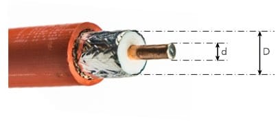
A length of coax cable exhibits a capacitance between the inner conductor and outer shield. The capacitance varies with the spacing of the conductors, the dielectric constant, and as a result the impedance of the line.

The lower the impedance, the higher the coax capacitance for a given length because the conductor spacing is decreased. The coax capacitance also increases with increasing dielectric constant, as in the case of an ordinary capacitor.
Where:
C = Capacitance in pF / metre
εr = Relative permeability of the dielectric
D = Inner diameter of the outer conductor
d = Diameter of the inner conductor
Inductance of coax cable
The inductance of the line can also be calculated. Again this is proportional to the length of the line.
However the inductance is independent of the dielectric constant for the material between the conductors, and is proportional to the logarithm of the ratio of the diameters of the two conductors.
Where:
L = Inductance in µH / metre
D = Inner diameter of the outer conductor
d = Diameter of the inner conductor
Coax impedance calculation
The impedance of the RF coax cable is chiefly governed by the diameters of the inner and outer conductors. On top of this the dielectric constant of the material between the conductors of the RF coax cable has a bearing. The relationship needed to calculate the impedance is given simply by the formula:
Where:
Zo = Characteristic impedance in Ω
εr = Relative permeability of the dielectric
D = Inner diameter of the outer conductor
d = Diameter of the inner conductor
Note: The units of the inner and outer diameters can be anything provided they are the same, because the equation uses a ratio.
Coax Impedance Calculator
Importance of coax impedance
The coax impedance is one of the major specifications associated with any piece of coax cable. As it will determine the matching within the system and hence the level of standing waves and power transfer, it is a crucial element. It is therefore necessary to ensure that the correct coax impedance is chosen for any system.
 Written by Ian Poole .
Experienced electronics engineer and author.
More Antenna & Propagation Topics:
EM waves
Radio propagation
Ionospheric propagation
Ground wave
Meteor scatter
Tropospheric propagation
Antenna basics
Cubical quad
Dipole
Discone
Ferrite rod
Log periodic antenna
Parabolic reflector antenna
Phased array antennas
Vertical antennas
Yagi
Antenna grounding
Installation guidelines
TV antennas
Coax cable
Waveguide
VSWR
Antenna baluns
MIMO
Return to Antennas & Propagation menu . . .


