Wire Wound Resistor: Wirewound Power Resistor
The wire wound resistor is often used in high power resistor applications or some other uses where its properties of low noise and power dissipation are needed.
Home » Electronic components » this page
Resistor Tutorial Includes:
Resistors overview
Carbon composition
Carbon film
Metal oxide film
Metal film
Wirewound
SMD resistor
MELF resistor
Variable resistors
Light dependent resistor
Thermistor
Varistor
Resistor colour codes
SMD resistor markings & codes
Resistor specifications
Resistor maximum voltage
Where & how to buy resistors
Standard resistor values & E series
The wire wound resistor is used in a variety of applications and in particular as a power resistor where larger amounts of power need to be dissipated.
As the name indicates, the wire wound resistor consists of a resistive wire that is wound around a former of nonconductive material. Normally the resistive wire is insulated, so that adjacent wires do not short together.
Wire wound resistors were one of the first types of resistor to be manufactured in the earliest days of electrical science and then wireless. They were superseeded in many applications by carbon resistors and then metal oxide and metal film resistors. However, today, wire would resistors are still used as the resistor of choice in many applications.

What is a wire wound resistor?
The wire wound resistor was one of the first forms of resistor to be used. The basic structure of the wirewound resistor has changed little over the years.
The resistor is constructed from resistance wire that is wound around a central core or former, that is usually made of ceramic.

Once wound, end caps are pressed onto the core and the resistance wire is welded to them to make proper contact. Finally the assembly is encapsulated to protect it from moisture and physical damage.
The construction of the wire wound resistors means that they can tolerate high temperatures and as a result they are used as high power resistors in many circumstances - but check the ratings to ensure they are sufficiently high power for the application.
The resistance of wire wound resistors is determined by a number of factors:
- Length of resistance wire
- Diameter of the resistance wire
- Resistivity of the resistance wire
To give a perspective of the figures involved, a 30 metre length of small diameter copper wire may have a resistance of only a few ohms. By contrast, using some resistance wire - a popular type is nickel chromium - the wire can be made only 30 cm long. This makes it viable to wind on a typical former that may be used in an electronic circuit.
If tight tolerance wire wound resistors are required, then the resistance wire chosen can have a lower resistance making the wire longer, and enabling its length to be cut more accurately as a proportion of the total length. If necessary the resistance can be trimmed on an individual basis.
Wirewound resistors come in a variety of packages and many are particularly suited for power resistor applications - some are contained within ceramic packages, while others are available within metallic packages that can be bolted to a metallic chassis or other forms of heat sink.

Wire wound resistor properties
Although wire would resistors are not nearly as widely used as other types like SMT resistors and leaded metal film resistors, they are an essential component for some particular areas of electronics where other types are totally not suitable or cannot perform as well.
As a result wire would resistors are used in a number of key areas because of their properties:
- High power applications: Wirewound resistors can dissipate significant amounts of power. Where dissipation levels rise above a watt or so, wire wound resistors come into their own. Not only does their technology enable them to withstand high power levels, but they can be designed to bolt to a heatsink so that they can dissipate even higher power levels safely - some are rated at up to 2.5kW.
- Very high tolerance applications : The fact that wire would resistors use resistance wire means that they can be they can be made with great precision - some have initial tolerances down to 0.005%. This can be very useful for applications such as use in measuring instruments.
- High temperature stability is needed: Not only can the wire would resistors be made very accurately, but they can also have a very high temperature stability, especially when compared to other types of resistor. The resistance wire used can be made to have a very low temperature coefficient of resistance, and this results in the final resistor having a low TCR. Advances in materials science have enabled the construction of devices with TCR values as low as 5 - 10 ppm / °C. This is dependent upon the metal or alloy used for the resistance wire.
- Long term stability: Another key feature of wire wound resistors is their long term stability. All resistors change their value with time, but wire wound ones change by very little. Figures of between 15 to 50ppm/year are often achieved because they are made with stable materials.
- Ability to absorb pulses: Unlike some forms of resistor, wire wound resistors are able to withstand high voltage pulses well. Their high thermal mass and the resilience of the wire in the resistors means that they are capable of absorbing energy levels well above their average ratings for short periods without sustaining damage or a change in resistance.
- Where customised requirements are needed: The way in which wire wound resistors are manufactured means that it is relatively easy to make customised devices with a resistance specified exactly by the customer for a particular requirement.
- Low noise applications: As a result of the fact that resistance wire is used, rather than other materials, these resistors are among the lowest current noise resistors available

Types of wirewound resistor
Wirewould resistors can be used in a variety of different applications and typically these fall into some major categories for which the construction of the resistor may change.
- Precision resistors: Precision wirewound resistors are used in a number of different applications. They can be used in items including test instrumentation - even being used multimeters, as well as measuring bridges, calibration equipment, and AF attenuators, etc. For these applications power dissipation is not an issue because for these applications the currents and voltage levels are small.
The resistors also need a low temperature coefficient of resistance must be low, possibly 5 ppm / °C. Long term stability should also be low, possibly less than 40 ppm per year. With figures like these basic resistance tolerance levels of ±0.01% can be chosen. Figures like these mean that the resistor will maintain the required resistance for a long period of time. - Power resistors: One of the major major uses of wire wound resistors is for power applications. Power capabilities can range up to 1 kW or 2.5kW. There are several types and these can be categorised by their package and construction:
- Silicone resin encapsulation: These encapsulations formats tend to be used for the lower power resistors. They are compact and can still withstand high temperatures: typically up to ~300°C, but often it is wise not to push them to the limit.
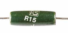
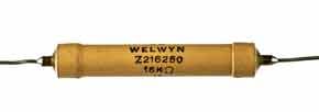
- Vitreous enamel coating: This type of coating has been widely used for power wirewound resistors for many years. These resistors are often specified for operation up to temperatures of ~400°C, but these temperatures are not advisable in most electronic equipment! The coating insulates well at lower temperatures, but it is less good as the temperature rises towards the top end of the range. Resistance values for these resistors range from ~1Ω up to ~10kΩ or so.
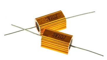
- Aluminium case: This type of construction is used for the highest power levels. The resistors have a ceramic core with a silicon resin coating which is then contained within an aluminium extrusion which is anodised (often a gold colour) to ensure good electrical insulation and to passivate the surface. The aluminium case of the resistor is typically manufactured with slight fins and the capability to be bolted onto a heatsink. The internals are also designed to conduct as much heat as possible to the aluminium case. A wide range of resistance values is available this type of resistor.
Wire wound resistor wire
As might be expected the wire used in wire would resistors governs many of its properties. Using different materials for the wire provides for different electrical properties: resistivity, temperature coefficient of resistance, long term stability, maximum operating temperature and the like.
The choice of material is important as the correct resistor wire will enable the optimum performance to be obtained for the resistor in a given role.
Many of the wire materials have familiar names as they have been used for many years as forms of resistance wire and therefore used within wirewound resistors.
Wires used are typically copper alloys, a variety of different iron alloys, nickel chromium alloys, silver alloys, and tungsten.
Wirewound resistor inductance & capacitance
Wire wound resistors are very good for low frequency and DC operation, but as the frequency of operation rises, the effects of inductance and capacitance become more noticeable.
The inductance arises from the fact that the resistor is effectively a coil of resistance wire and is effecting an inductor. The capacitance occurs between the different turns on the coil, etc.
As the frequency of operation rises above 100kHz or so, these affects can become significant and alter the operation of the circuit.
Normally the wirewound resistor is wound as an ordinary coil on a ceramic former and this is more than adequate for most types of operation. However if low inductance and capacitance are needed, there are other methods that can be used to hep reduce, although not eliminate the inductance and capacitance.
There are methods that can be employed to reduce the inductance:
- Bifilar winding: One method that can be adopted is to use bifilar wire, i.e. two separate wires run together. These can then be joined at the far end. The concept is that by running two wires together in this way, the current will run in exactly opposite directions and the fields will cancel. Although not perfect it significantly reduces the inductance, but as two wires are run in close proximity the unwanted capacitance increases.
- Ayrton-Perrry winding: The is an unusual form of winding. As the wire enters the resistor coil,, it splits into two, one half being wound in one direction and the other half in the reverse sense. By winding in this manner, the wires are arranged so that the current flows in opposing directions, thereby reducing the inductance. Also the wire do not run alongside each other in the same way as with the bifilar winding, and therefore there is little increase into e capacitance.
Self inductance and capacitance will always be an issue with wirewound resistors. As a result they are seldom used for applications where they are used at high or radio frequencies. Only when they are used in a section of the circuit not carrying RF would they be used. The specialist winding techniques tend to be used only as a last resort. It is much better to use a different resistor technology if high frequencies are present across the resistor.
Wirewound resistors are used quite extensively. They are particularly used as high power resistors where larger levels of power need to be dissipated. They are widely used in many power applications; not only are they physically larger than many other types of resistor, but having a wire conductor and a ceramic former, they are for more suited to being a high power resistor than other types more widely found.
Unfortunately their construction means that they are much more expensive than the much smaller resistors normally used.
Wirewound resistors are also used where very close tolerance and high temperature stability is needed. The wire typically has a better temperature coefficient of resistance than many other types of resistor, although many these days are very good.
 Written by Ian Poole .
Experienced electronics engineer and author.
More Electronic Components:
Batteries
Capacitors
Connectors
ADC
DAC
Diodes
FET
Inductors
Memory types
Phototransistor
Quartz crystals
Relays
Resistors
RF connectors
Switches
Surface mount technology
Thyristor
Transformers
Transistor
Unijunction
Valves / Tubes
Return to Components menu . . .


