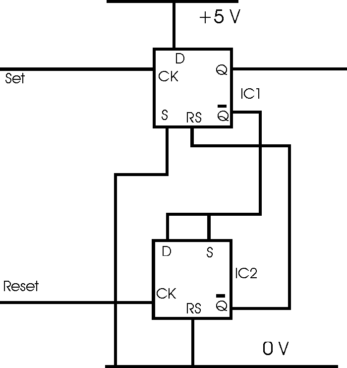
Edge triggered flip flop circuit
- the circuit for an edge triggered RS flip flop using two D types as used by many engineers in logic circuit design
Logic / Digital Design Includes:
Logic gate types
Logic truth table
How to convert NAND / NOR gates with inverters
Exclusive OR, XOR
RS Flip-Flop
Edge triggered RS Flip-Flop
Programmable inverter
D-type frequency divider
The simple RS flip flop logic circuit using two electronic logic gates is quite adequate for most purposes. However there are some instances when this may not meet the requirements and an edge triggered flip flop may be needed. An edge triggered flip flop gives a more exact switching, and this may be required in some logic circuits. IN instances where an edge triggered flip flop is needed, the logic circuit shown below provides a simple and effective implementation.

Edge Triggered R-S Flip Flop
When there is a low to high transition on the set input to the circuit on CK1 this sets the Q1 output to high. A low to high on CK2 then sets Q1 to low.
Circuit considerations
When using this logic circuit it is necessary to adopt a few precautions otherwise there can be problems that may be difficult to see and solve. The very nature that this logic circuit is edge triggered means that great care must be taken to ensure that no stray edges are able to spuriously trigger the circuit. Even very short but fast pulses will be sufficient to trigger the circuit. These may be very difficult to track or see using an oscilloscope, especially if they are random in nature. To ensure this does not happen, the supply should be well decoupled, and in addition to this the wiring should be routed in such a way that no stray pulses should be picked up. Additionally attention should be paid to the earthing of the logic devices does not introduce any problems.
Edge triggered flip flop applications
This type of circuit may have a number of applications in logic circuit design. One could be as a phase detector in a phase locked loop. The two signals will be seeking to either set or reset the circuit, and the length of time that Q is high will be dependent upon the phase difference between the two signals.
 Written by Ian Poole .
Experienced electronics engineer and author.
More Digital Logic and Embedded Topics:
FPGA programming
Embedded systems
How a computer works
Logic circuit design basics
Logic / circuit design guidelines
Return to Digital / Logic / Processing menu . . .


