Electronically Programmable Inverter
How to make an electronically programmable or controlled logic inverter using a single exclusive OR gate.
Logic / Digital Design Includes:
Logic gate types
Logic truth table
How to convert NAND / NOR gates with inverters
Exclusive OR, XOR
RS Flip-Flop
Edge triggered RS Flip-Flop
Programmable inverter
D-type frequency divider
This electronic circuit is a particularly elegant for its simplicity. Using a single NOR gate it provides the ability to either invert or not invert a logic signal.
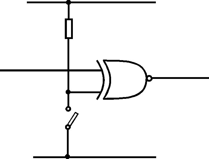
Simply using the truth table for the exclusive OR function it can be seen that when there is a low on one input to the exclusive OR gate, the signal on the other input is passed through the circuit and not inverted. When the signal on one input is a high, then the signal on the other is inverted at the output.
| Exclusive OR / NOR Truth Table | |||
|---|---|---|---|
| A | B | Ex-OR Output |
Ex-NOR Output |
| 0 | 0 | 0 | 1 |
| 0 | 1 | 1 | 0 |
| 1 | 0 | 1 | 0 |
| 1 | 1 | 0 | 1 |
As seen from the electronic circuit below, it consists of an exclusive NOR gate, a pull up resistor and a switch. The control line could come from an external source such as another gate. In this case there would be no need for the pull up resistor, and the circuit would simply consist of the single gate held within the integrated circuit.

Programmable Inverter using Exclusive OR gate
 Written by Ian Poole .
Experienced electronics engineer and author.
More Digital Logic and Embedded Topics:
FPGA programming
Embedded systems
How a computer works
Logic circuit design basics
Logic / circuit design guidelines
Return to Digital / Logic / Processing menu . . .


