GPIB Connectors
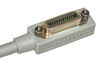
The Amphenol type 57 connector is used as the main standard for GPIB cables and interconnections, although some applications have used D-Types or other formats.
GPIB / IEEE 488 Bus Includes:
GPIB / IEEE 488 bus
GPIB operation / commands / protocol
IEEE 488.2
How to Use GPIB / IEEE 488
GPIB / IEEE 488 cables
GPIB / IEEE 488 connectors
GPIB / IEEE 488 pinout / pin connections
The connector used for the GPIB / IEEE 488 bus is standard across the industry.
The GPIB system uses the 24-way Amphenol 57 series type.
This connector provides an ideal physical interface for the standard being robust and providing a good number of connections.
The robust nature of the connector is essential because it is required to survive general laboratory usage where the connectors may not be treated with much care, and also they may be required to operate in less than clean environments.
GPIB connector system
The Amphenol 57 series connector consists of a basic metal 'D' shaped shroud or shell that provides mechanical rigidity and this holds in place an insulating plastic insert. This is used to hold the individual contacts in place.

There are two main uses for the connectors:
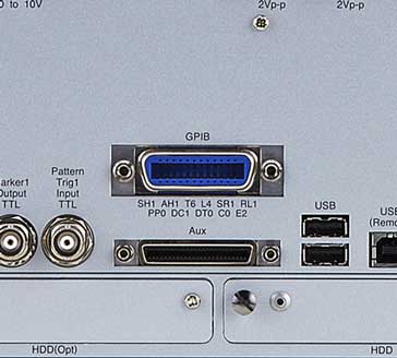
- Equipment: The connector used on any equipment is the female variety. This may be a solder bucket variety, a direct PCB mount one or any option that is needed.

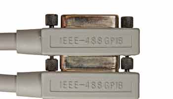
GPIB connector on modern test equipment showing the female version of the connector - Cables: The cables use a back to back male-female arrangement allowing multiple cables to be piggy backed on one another. This helps the physical setting up of the bus and prevents complications with special connection boxes or star points, etc.

Screw-lock system
An additional advantage of the GPIB connector is that it has a screw-lock. In this way, once the connectors have been mated the screw-lock can be used to secure the connectors together. In this way movements of the GPIB cables are less likely to cause any intermittent connections. With complicated electronics systems such as automatic test systems, intermittent cable connections can cause significant problems which can be difficult to isolate and cure. By using a GPIB connector that has a screw-lock this problem can be largely overcome.
There are two different types of screwlock used on the GPIB connectors. These do not mate with each other so care may be needed when using legacy products.
- UTS: These were the original screw-locks used but they are now largely obsolete and difficult to obtain. The UTS screws were a standard widely used in the USA and Canada. By convention, when used for GPIB applications they were are normally finished with a chrome / silver coloured finish.
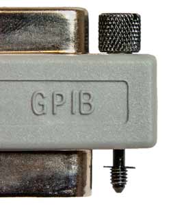
- Metric: Metric M3.5 x 0.6 are now the main form of screw-lock used. By convention these have a black finish.

The photo shows the newer black metric versions of the screw-lock, sowing how they are contained within a cable connector. Equipment based connectors just have a captive nut into which these screwlocks can be fixed.
Other connector options
The IEC-60625 standard also allowed for the use of the more familiar 25-pin version of the D-sub-miniature connectors.
These are the same type or series that are used for applications such as the serial printer port PCs. However this connector did not gain any significant level of market acceptance, and has all but disappeared from use in this application.
 Written by Ian Poole .
Experienced electronics engineer and author.
More Test Topics:
Data network analyzer
Digital Multimeter
Frequency counter
Oscilloscope
Signal generators
Spectrum analyzer
LCR meter
Dip meter, GDO
Logic analyzer
RF power meter
RF signal generator
Logic probe
PAT testing & testers
Time domain reflectometer
Vector network analyzer
PXI
GPIB
Boundary scan / JTAG
Data acquisition
Return to Test menu . . .


