LabVIEW VIs, or LabVIEW Virtual Instruments form the key element within the overall environment.
The virtual instrument provides a visual method of creating the algorithm algorithm and it can be used on its own or within a larger overall programme. In one aspect, the LabVIEW Virtual Instrument could be likened to a subroutine used in some programming languages.
LabVIEW VI basics
The LabVIEW VI consists of two main elements:
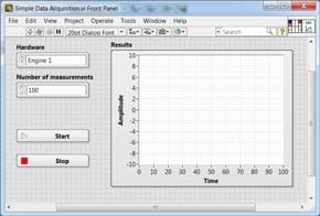
VI Front Panel: The LabVIEW front panel is what the user of the completed application will see. It enables them to interact with the VI, inputting controls and also seeing results. It can be likened to the font panel of a test instrument or other piece of equipment.
The LabVIEW VI front panel can be built up from scratch using the palette of different controls, indicators and data types.
Example of a LabVIEW VI Front Panel
LabVIEW VI front panels can be completely customized. By having a totally customized front panel, it is possible to simplify the operation to provide exactly what is needed without unnecessary controls that may not be required.
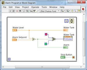
VI block diagram: The LabVIEW VI block diagram is where the functionality of the VI is programmed in G. The block diagram defines the functionality whilst also providing a visual representation of it. In this way the block diagram is similar to a flow diagram within a programme.
Example of a LabVIEW VI Block Diagram
There is an associated functions palette within the block diagram space where all the elements needed to build the programme can be found. This enables swift accurate programming to be achieved.
Written by Ian Poole . Experienced electronics engineer and author.
Fact of the day: It was on this day in 1993 that the Intel Corporation shipped the first Pentium chips. These chips, also called the 80586 were 64 bit devices with a 60 MHz clock rate and capable of 100+ MIPS
Quote:The intention of the Holy Ghost is to teach us how one goes to heaven, not how heaven goes. Galileo Galilei
Point to ponder: A meeting is an event at which the minutes are kept and the hours are lost.

 Written by Ian Poole .