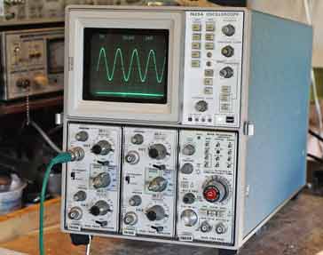
Analogue Storage Oscilloscope
The analogue or analog storage oscilloscope provided a method of capturing, storing and displaying waveforms.
Scope types includes:
Analogue scope
Analogue storage scope
Digital phosphor scope
Digital scope
USB / PC scope
Mixed Signal Oscilloscope MSO
Sampling scope
Oscilloscope Tutorial Includes:
Oscilloscope basics
Oscilloscope types
Specifications
USB vs bench-top scope
How to use an oscilloscope
Scope triggering
Oscilloscope probes
Oscilloscope probe specifications
Analogue storage oscilloscopes were used when it was necessary to store waveforms for visualisation later. These analog storage oscilloscopes were very expensive and as a result they were generally only used for specialist applications.
The analog storage oscilloscope provided the capability for displays that would normally only persist for a fraction of a second could be stored for possibly several minutes.
By the standards of todays digital oscilloscopes that can easily store waveforms, these analogue storage oscilloscopes were very crude in terms of their performance, and despite this they were very expensive. However they were the only way in which displays could be stored for longer than the natural persistence of the cathode ray tube screen.
Analogue scope applications
Analogue storage oscilloscopes were needed in a variety of different applications.
- Long period waveforms: One application for a analogue storage oscilloscope occurred when it might have been necessary to display a signal with a very long period. It must be remembered that time a display remained visible after a scan was relatively short. The cathode ray tube operation normally relied on the repeated refresh of the screen as the scan was repeated many times a second. Thus the normal persistence of a display would mean that the trace for a long period waveform would decay before it was complete.
- Displaying single shot waveforms: Another instance where a storage capability would be needed was for single shot applications where the single trace would need to be displayed over a period of time to examine the trace.

For these and many other situations, it is necessary to have a storage facility on the scope where it can display the trace for longer than would normally be possible.
Analogue oscilloscope technology
Analogue storage scopes use a special cathode ray tube with a long persistence facility. A special tube with an arrangement to store charge in the area of the display where the electron beam had struck, thereby enabling the fluorescence to remain for much longer than attainable on normal displays.
These cathode ray tubes had the facility to vary the persistence, although if very bright traces were held over long periods of time, they would have the possibility of permanently burning the trace onto the screen. Accordingly these storage displays needed to be used with care.
In terms of the actual analogue storage oscilloscope technology, the special cathode ray tubes used rely on a technique called secondary emission.
The storage capability utilises the fact that using the ordinary writing electron beam not only causes the phosphor to illuminate, but the kinetic energy of the electron beam also knocks other electrons loose from the phosphor surface - this is the secondary emission process.
When electrons have been freed from the surface of the illuminating phosphor they leave a net positive charge in that region.
This fact is used by analogue storage oscilloscopes as their cathode ray tubes contain one or more secondary electron guns, or "flood guns." These provide a steady flood of low-energy electrons that travel towards the phosphor screen.
Flood guns electrons are emitted in such a way that they cover the entire screen in as uniform a manner as possible. When they travel along the tube, the electrons from the flood guns are more strongly drawn to the areas where there is a positive charge as dissimilar potentials attract. According the areas of the phosphor screen where the writing gun has left a net positive charge attracts more electrons and as a result the illuminating electrons from the flood guns re-illuminate the phosphor in the positively charged areas of the phosphor, i.e. the screen.
It is necessary to ensure that the electrons from the flood guns have just sufficient energy to release one electron from the screen. In this way the positive charge is preserved in the area and the pattern on the screen remains.
As can be imagined, the system is far from perfect, and over time the stored image becomes blurred and less distinct. Nevertheless the storage capability enables the waveform to be displayed on the screen for much longer than would otherwise become possible.
 Written by Ian Poole .
Experienced electronics engineer and author.
More Test Topics:
Data network analyzer
Digital Multimeter
Frequency counter
Oscilloscope
Signal generators
Spectrum analyzer
LCR meter
Dip meter, GDO
Logic analyzer
RF power meter
RF signal generator
Logic probe
PAT testing & testers
Time domain reflectometer
Vector network analyzer
PXI
GPIB
Boundary scan / JTAG
Data acquisition
Return to Test menu . . .


