Oscilloscope Probe Specifications & Parameters
The oscilloscope probe, or scope probe performance can determine the overall performance of the scope test system - it is therfore very important to know the relevant specifcations and choose the scope probe accordingly.
Oscilloscope Tutorial Includes:
Oscilloscope basics
Oscilloscope types
Specifications
USB vs bench-top scope
How to use an oscilloscope
Scope triggering
Oscilloscope probes
Oscilloscope probe specifications
Scope probes include:
Oscilloscope probes
Probe compensation
Oscilloscope probe specifications
Understanding the oscilloscope probe specifications is key to choosing the right probe for any given oscilloscope.
Knowing whth the key scope probe specifications are and what they mean is important when selecting a scope probe.

Oscilloscope probe specifications
We have compiled a list of some of the more important oscilloscope probe specifications or specs which are detailed below:
- Accuracy: The accuracy of any oscilloscope probe is of great importance. Typically for voltage sensing probes the accuracy refers to the attenuation of the signal by the probe as in the case of a 10X probe. The accuracy will be dependent upon the accuracy of the series resistor in the probe, but it is also dependent upon the accuracy of the input resistance of the scope. Accordingly, the scope probe accuracy specification is only correct or applicable when the probe is being used with an oscilloscope having the assumed input resistance.
- Attenuation: This scope probe specification details the ratio of the output signal to the input signal in terms of voltage. Common scope probe attention levels are 1 (i.e. no attenuation) and 10 although probes with attenuation levels of 100 are occasionally available for specialist applications. These are generally marked x1, x10 etc where the figure indicates the multiplication of input resistance. A x10 probe will give ten times the input impedance but 1/10 of the voltage. Sometimes probes may be switchable between 1X and 10X.
- Bandwidth: The maximum bandwidth is the frequency at which the response falls by 3dB (i.e. -3dB) of the low frequency value. When choosing a scope probe, the value of the bandwidth should be well above that of the maximum frequencies anticipated, otherwise errrors will be introduced into the results. It is also worth choosing a scope probe with a bandwidth higher than the scope itself. In this way the full potential of the scope can be used. As a general rule, for accurate amplitude measurements, the bandwidth of the scope probe and also the oscilloscope should be five times greater than the frequency of the waveform being measured. This enables any harmonics of the fundamental signal to be adequately captured.
- Cable length: It is necessary to consider the length of the cable. The longer the cable, often the lower the bandwidth. However it is still necessary to ensure that the length is sufficient to accommodate easy working. Common cable lengths are: 1.3m, 2m, and longer lengths for higher voltage probes where it may be necessary for greater distances between the equipment being tested and the scope and people using the scope.
- Common mode rejection ratio, CMMR: This probe specification is applicable to differential probes. It is a measure of the ability of the probe to reject any signals that are common to both inputs.
- Compensation range: The compensation range of the scope probe is the range of input capacitance of the oscilloscope that the probe can compensate, i.e. it can be used with oscilloscopes with input capacitance levels within a given range.
- IEC 1010: This refers to the safety rating for the scope probe. Different categories are used for different types of equipment.
- Input capacitance: This is the typical input capacitance of the probe. It will depend to some degree on the capacitance of the scope, and the adjustment of the probe capacitor, but typical values for the overall input capacitance can be given.
- Input resistance: This is the system input resistance, i.e. the sum of any resistor in the probe (9 M Ohm for a 10X probe), plus the scope input resistance (typically 1 M Ohm)
- Input voltage: A maximum input voltage is specified. This is the highest voltage that the probe should be connected to. It will include both DC and AC components and will effectively mean the peak instantaneous voltage that may be seen by the probe. While the voltages that can be tolerated by passive probes may extend into hundreds of volts, active probes may only tolerate maximum input voltages in the region of a few tens of volts.
- Readout detection: When using some scope probes on particular scopes, it is possible that they detect the attenuation level and adapt the readout accordingly. If this feature is required, it is necessary to ensure that the scope and probe are compatible.
- Differential voltage: This probe specification is applicable to differential probes. It is the voltage difference between the two points on the probe.
- Rise time: This is the time required for the leading edge of a pulse to rise from 10% to 90% of its final value. For accurate pulse rise and fall time measurements on, the overall rise time of the system (scope and probe combined) should be three to five times faster than the fastest transition to be measured.
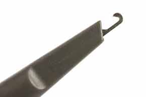
- Tip or head style: Details of the scope probe tip or head style may also be given. Reference to the manufacturer's specifications may be needed. Typically the clip will have a curved end that will clamp into the wire or test point.

Oscilloscope probe tip
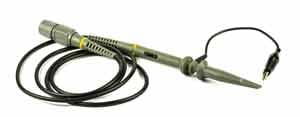
Oscilloscope probes are an essential when any oscilloscope is used. They enable the electronic circuit design under test to be probed so that the required signals can be accessed and seen on the scope screen.
Accordingly the performance of the scope probe is of great importance. Not only must be be able to access the circuit, but it must transfer the signal from the circuit under test, to the scope itself. It must achieve this with the minimum of distortion of the signal. It is for this reason that the performance of the probe is key. Poor performance will limit the performance of the scope.
Accordingly it is of no use to have a high performance scope with a low performance probe. It is for this reason that the performance and specification of the scope probe is of paramount importance.
 Written by Ian Poole .
Experienced electronics engineer and author.
More Test Topics:
Data network analyzer
Digital Multimeter
Frequency counter
Oscilloscope
Signal generators
Spectrum analyzer
LCR meter
Dip meter, GDO
Logic analyzer
RF power meter
RF signal generator
Logic probe
PAT testing & testers
Time domain reflectometer
Vector network analyzer
PXI
GPIB
Boundary scan / JTAG
Data acquisition
Return to Test menu . . .


